
Page 94 - Electromechanical Devices and Components Illustrated Sourcebook
P. 94
56 Electromechanical Devices & Components Illustrated Sourcebook
Contacts of overloads are supplied on the outputs. The overloads will
Contactor
Switched be discussed in greater detail in Chapter 8.
Terminals For greater safety, the circuit that controls the coil, or con-
High-Current trol circuit, uses a lower voltage than the line voltage. In these
Motor
cases the contactor coil is a low-voltage unit and a step-down
transformer is added to the controller. The low-control voltage
M Power is much safer and easier to work with. Figure 4-64 shows a
Auxiliary Contacts Contactor
Overload Protection
Off Button On Button
C
220/480 VAC
3 Phase
Coil Terminals Coil
115 VAC Coil
Figure 4-61 Contactor Schematic with Auxiliary Contacts
C
M
Motor
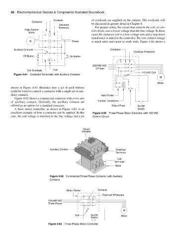
shown in Figure 4-61 illustrates how a set of push buttons
could be wired to control a contactor with a single set of aux-
iliary contacts. Input Fuses
Figure 4-62 shows a commercial contactor with a two sets
of auxiliary contacts. Generally, the auxiliary contacts are Control Transformer
offered as an option for a standard contactor. Output Fuse On/Off
A basic motor controller, as shown in Figure 4-63, is an Switch
excellent example of how a contactor can be applied. In this Figure 4-64 Three-Phase Motor Controller with 120 VAC
case, the coil voltage is matched to the line voltage and a set Control Circuit
Visual
Indicator
Auxillary Contact Switched
Terminals
Coil
Terminals
Base
Figure 4-62 Commercial Three-Phase Contactor with Auxiliary
Contacts
Motor Starter Contacts
Overload W/Heaters
220/480 VAC
Three Phase
C
M
Coil On/Off Motor
Switch
Figure 4-63 Three-Phase Motor Controller