
Page 95 - Electromechanical Devices and Components Illustrated Sourcebook
P. 95
Chapter 4 Electrical Controls 57
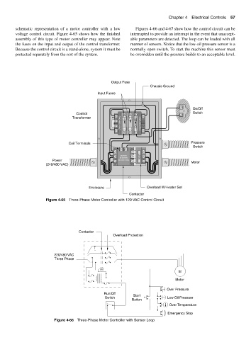
schematic representation of a motor controller with a low Figures 4-66 and 4-67 show how the control circuit can be
voltage control circuit. Figure 4-65 shows how the finished interrupted to provide an interrupt in the event that unaccept-
assembly of this type of motor controller may appear. Note able parameters are detected. The loop can be loaded with all
the fuses on the input and output of the control transformer. manner of sensors. Notice that the low oil pressure sensor is a
Because the control circuit is a stand-alone, system it must be normally open switch. To start the machine this sensor must
protected separately from the rest of the system. be overridden until the pressure builds to an acceptable level.
Output Fuse
Chassis Ground
Input Fuses
On/Off
Control Switch
115/120 VAC
Transformer
240/480 VAC
Coil Terminals Pressure
Switch
MOTOR RESET
STARTER
Power 120 VAC COIL
(240/480 VAC) Motor
Enclosure Overload W/Heater Set
Contactor
Figure 4-65 Three-Phase Motor Controller with 120 VAC Control Circuit
Contactor
Overload Protection
220/480 VAC
Three Phase
C
M
Motor
Over Pressure
Run/Off Start
Switch Low Oil Pressure
Button
Over Temperature
Emergency Stop
Figure 4-66 Three-Phase Motor Controller with Sensor Loop