
Page 97 - Electromechanical Devices and Components Illustrated Sourcebook
P. 97
Chapter 4 Electrical Controls 59
On/Off/Auto
Switch
Power
2.5
2.0 3.0
1.5 3.5
1.0 4.0 10 Amp DC
4.5 120 VAC Coil
.5
0 5.0
Seconds
Fault
Input Fuses
Control Emergency
Transformer Stop
115/120 VAC
Enclosure 240/480 VAC
Output Fuse
Pressure Switch
Coil
Terminals
Sensor Loop
MOTOR
STARTER RESET
120 VAC COIL
Motor
Power
(240/480 VAC)
Heater Set
Contactor
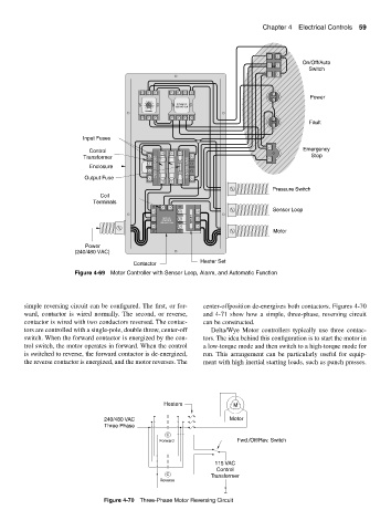
Figure 4-69 Motor Controller with Sensor Loop, Alarm, and Automatic Function
simple reversing circuit can be configured. The first, or for- center-offposition de-energizes both contactors. Figures 4-70
ward, contactor is wired normally. The second, or reverse, and 4-71 show how a simple, three-phase, reversing circuit
contactor is wired with two conductors reversed. The contac- can be constructed.
tors are controlled with a single-pole, double throw, center-off Delta/Wye Motor controllers typically use three contac-
switch. When the forward contactor is energized by the con- tors. The idea behind this configuration is to start the motor in
trol switch, the motor operates in forward. When the control a low-torque mode and then switch to a high-torque mode for
is switched to reverse, the forward contactor is de-energized, run. This arrangement can be particularly useful for equip-
the reverse contactor is energized, and the motor reverses. The ment with high inertial starting loads, such as punch presses.
Heaters M
240/480 VAC Motor
Three Phase
C
Forward Fwd./Off/Rev. Switch
115 VAC
Control
C Transformer
Reverse
Figure 4-70 Three-Phase Motor Reversing Circuit