
Page 101 - Electromechanical Devices and Components Illustrated Sourcebook
P. 101
Chapter 4 Electrical Controls 63
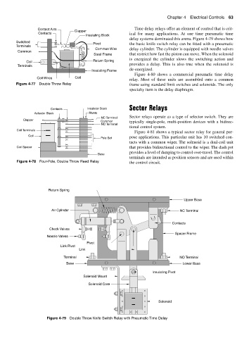
Contact Arm Time delay relays offer an element of control that is crit-
Clapper
Contacts ical for many applications. At one time pneumatic time
Insulating Block
delay systems dominated this arena. Figure 4-79 shows how
Switched
Pivot the basic knife switch relay can be fitted with a pneumatic
Terminals
Common Wire delay cylinder. The cylinder is equipped with needle valves
Common
Steel Frame that restrict how fast the piston can move. When the solenoid
is energized the cylinder slows the switching action and
Coil Return Spring
Terminals provides a delay. This is also true when the solenoid is
de-energized.
Insulating Frame
Figure 4-80 shows a commercial pneumatic time delay
Coil Wires Coil
relay. Most of these units are assembled onto a common
Figure 4-77 Double Throw Relay frame using standard limit switches and solenoids. The only
specialty item is the delay diaphragm.
Sector Relays
Contacts Insulator Stack
Actuator Stack Rivets
Sector relays operate as a type of selector switch. They are
NC Terminal
Clapper
Common typically single-pole, multi-position devices with a bidirec-
NO Terminal
tional control system.
Coil Terminals
Figure 4-81 shows a typical sector relay for general pur-
Coil
Pole Set pose applications. This particular unit has 10 switched con-
tacts with a common wiper. The solenoid is a dual-coil unit
Coil Spacer that provides bidirectional control to the wiper. The dash pot
provides a level of damping to control over-travel. The control
Base
terminals are intended as position sensors and are used within
Figure 4-78 Four-Pole, Double Throw Reed Relay the control circuit.
Return Spring
Upper Base
Air Cylinder NC Terminal
Contacts
Check Valves
Spacer Frame
Needle Valves
Pivot
Link Pivot
Link
Terminal NO Terminal
Base Lower Base
Insulating Pivot
Solenoid Mount
Solenoid Core
Solenoid
Figure 4-79 Double Throw Knife Switch Relay with Pneumatic Time Delay