
Page 104 - Electromechanical Devices and Components Illustrated Sourcebook
P. 104
66 Electromechanical Devices & Components Illustrated Sourcebook
Common Terminals
Base
Wiper
3 4 5 6 7
Beryllium Copper 0 1 8 9 Contacts
Return Spring
Hold Ratchet
Reset Cam
Pivot
Stop Pins
Reset Plate
Advance Solenoid
Reset Solenoid
Advance Ratchet
Reset Spring
Figure 4-85 Communications Sector Relay
Insulating Block
Contact Arm
Clapper Contacts
Upper Solenoid Latch Paw
Common
Latch Solinoid
Terminals
Latch
Upper Base Terminals
Terminal Activate
Terminals
Link Pivot Upper Contacts Insulating Frame
Pivot Spacer Frame Latch Spring Return Spring
Activate Solenoid
Links Figure 4-87 Commercial Latching Relay
Lower Contacts
Terminal Terminal
Base Lower Base
Insulating Pivot
Solenoid Mount
Switched Contacts
Solenoid Core
Lower Solenoid
Relay
On Button
Off Button
Figure 4-86 Double Throw, Latching Knife Switch Relay
Control
Power
Figure 4-88 Holding Circuit
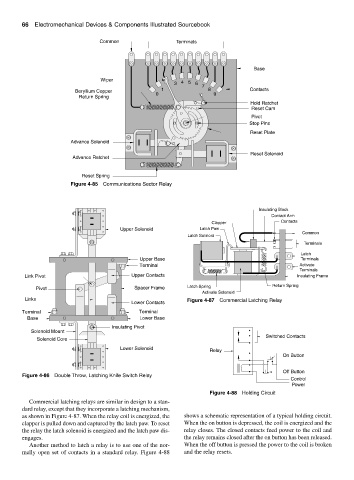
Commercial latching relays are similar in design to a stan-
dard relay, except that they incorporate a latching mechanism,
as shown in Figure 4-87. When the relay coil is energized, the shows a schematic representation of a typical holding circuit.
clapper is pulled down and captured by the latch paw. To reset When the on button is depressed, the coil is energized and the
the relay the latch solenoid is energized and the latch paw dis- relay closes. The closed contacts feed power to the coil and
engages. the relay remains closed after the on button has been released.
Another method to latch a relay is to use one of the nor- When the off button is pressed the power to the coil is broken
mally open set of contacts in a standard relay. Figure 4-88 and the relay resets.