
Page 105 - Electromechanical Devices and Components Illustrated Sourcebook
P. 105
Chapter 4 Electrical Controls 67
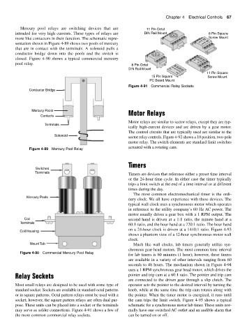
Mercury pool relays are switching devices that are 11 Pin Octal
intended for very high currents. These types of relays are DIN Rail Mount 8 Pin Square
more like contactors in their function. The schematic repre- Screw Mount
sentation shown in Figure 4-89 shows two pools of mercury
that are in contact with the terminals. A solenoid pulls a
conductor bridge down into the pools and the switch is
closed. Figure 4-90 shows a typical commercial mercury
pool relay. 8 Pin Octal
DIN Rail Mount
11 Pin Square
15 Pin Square Screw Mount
PC Board Mount
Figure 4-91 Commercial Relay Sockets
Conductor Bridge
Mercury Pools Motor Relays
Contacts
Motor relays are similar to sector relays, except they are typ-
Terminals
ically high-current devices and are driven by a gear motor.
The control circuits that are typically used are similar to the
Solenoid
sector relay controls. Figure 4-92 shows a 10 position, two-pole
motor relay. The switch elements are standard limit switches
actuated with a rotating cam.
Figure 4-89 Mercury Pool Relay
Timers
Switched
Terminals
Timers are devices that reference either a preset time interval
or the 24-hour time cycle. In either case the timer typically
trips a limit switch at the end of a time interval or at different
times during the day.
The most common electromechanical timer is the ordi-
Mercury Pools
nary clock. We all have experience with these devices. The
typical wall clock uses a synchronous motor which operates
in reference to the utility company’s 60 Hz AC power. The
motor usually drives a gear box with a 1 RPM output. The
Coil second hand is driven at a 1:1 ratio, the minute hand at a
Terminals
60:1 ratio, and the hour hand at a 720:1 ratio. The hour hand
on a 24-hour clock is driven at a 1440:1 ratio. Figure 4-93
Coil Housing
shows a phantom view of a 12-hour synchronous motor wall
clock.
Mount Tab Much like wall clocks, lab timers generally utilize syn-
chronous gear head motors. The most common time interval
Figure 4-90 Commercial Mercury Pool Relay
for lab timers is 60 minutes (1 hour); however, these timers
are available in a variety of other intervals ranging from 60
seconds to 48 hours. The mechanism shown in Figure 4-94
uses a 1 RPM synchronous gear head motor, which drives the
Relay Sockets pointer and trip cam at a 60:1 ratio. The pointer and trip cam
are connected to the driven gear through a slip clutch. The
Most small relays are designed to be used with some type of operator sets the pointer to the desired interval by turning the
standard socket. Sockets are available in standard octal patterns knob, while at the same time the trip cam rotates along with
or in square patterns. Octal pattern relays must be used with a the pointer. When the timer motor is energized, it runs until
socket; however, the square pattern relays are often dual pur- the cam trips the limit switch. Figure 4-95 shows a typical
pose. These units can be placed into a socket or the terminals schematic for a synchronous motor lab timer. These units nor-
may serve as solder connections. Figure 4-91 shows a few of mally have one switched AC outlet and an audible alarm that
the more common commercial relay sockets. can be turned on or off.