
Page 106 - Electromechanical Devices and Components Illustrated Sourcebook
P. 106
68 Electromechanical Devices & Components Illustrated Sourcebook
Common
Two-Pole Limit Switch
Switched Pole
Common Base Plate Control Pole
Conductor
Rotating Cam
Common Conductor
Gear Head
DC Motor
Shaft
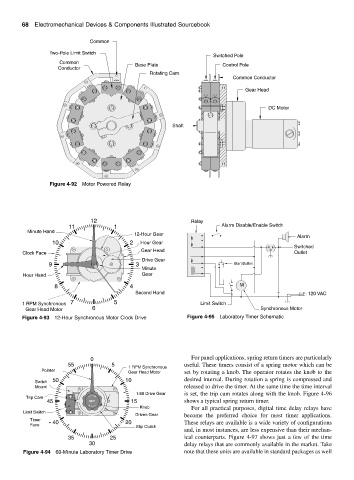
Figure 4-92 Motor Powered Relay
12 Relay
11 1 Alarm Disable/Enable Switch
Minute Hand
12-Hour Gear
Alarm
10 2 Hour Gear
Switched
Gear Head
Clock Face Outlet
Drive Gear
9 3 Start Button
Minute
Hour Hand Gear
8 4 M
Second Hand 120 VAC
1 RPM Synchronous 7 5 Limit Switch
Gear Head Motor 6 Synchronous Motor
Figure 4-93 12-Hour Synchronous Motor Clock Drive Figure 4-95 Laboratory Timer Schematic
0 For panel applications, spring return timers are particularly
55 5 useful. These timers consist of a spring motor which can be
1 RPM Synchronous
Pointer Gear Head Motor set by rotating a knob. The operator rotates the knob to the
Switch 50 10 desired interval. During rotation a spring is compressed and
Mount released to drive the timer. At the same time the time interval
1:60 Drive Gear is set, the trip cam rotates along with the knob. Figure 4-96
Trip Cam
45 SET 15 shows a typical spring return timer.
Knob For all practical purposes, digital time delay relays have
Limit Switch
Driven Gear become the preferred choice for most timer applications.
Timer 40 20
Face These relays are available is a wide variety of configurations
Slip Clutch
and, in most instances, are less expensive than their mechan-
35 25 ical counterparts. Figure 4-97 shows just a few of the time
30 delay relays that are commonly available in the market. Take
Figure 4-94 60-Minute Laboratory Timer Drive note that these units are available in standard packages as well