
Page 111 - Electromechanical Devices and Components Illustrated Sourcebook
P. 111
Chapter 4 Electrical Controls 73
Fired Filler
Ceramic
Housing
Schematic Symbol
Carbon
Plastic Case
Electrodes
Leads
Bare Wire
Figure 4-109 High-Wattage Ceramic Resistor
Figure 4-107 Carbon Resistor
Screw Lug
Aluminum Case
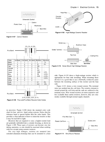
2%, 5%, & 10%
Solder Terminal
Five Band
Top View
Cooling Fins
Color 1st Band 2nd Band 3rd Band Multiplier Tolerance
Black 1 1 1 1 1%
Side View End View
Brown 2 2 2 10 2%
Red 3 3 3 100 - Figure 4-110 Screw Mount High Wattage Resistor
Orange 4 4 4 1K -
Yellow 5 5 5 10K -
Green 5 5 5 100K 0.5%
Blue 6 6 6 1M 0.25%
sink. Figure 4-110 shows a high-wattage resistor which is
Violet 7 7 7 10M 0.10%
appropriate for heat sink mounting. When mounting these
Gray 8 8 8 - 0.05%
devices it is a good idea to use a thermally conductive paste
White 9 9 9 - -
Gold - - - 0.1 5% between the mounting surface of the resistor and the heat
Silver - - - 0.01 10% sink.
Figure 4-111 shows a wire wound resistor. The terminal
wires are molded into the coil form. The resistive element is
wound around the coil form and the ends are soldered to the
terminal wires. Wire wound resistors are more expensive and
Four Band
less available than carbon resistors, however, they are com-
monly available through normal supply channels.
0.1%, 0.25%, 0.5%, & 1%
Figure 4-108 Four-and-Five Band Resistor Color Codes
its precision. Figure 4-108 shows the standard color code
chart for four- and five- band coding systems. Notice that the
Schematic Symbol
tolerance band is spaced further then the value bands. This
provides a clear indicator of how to orient the resistor so that Fine Wire Coil
it may be read left-to-right.
Resistors that are required to carry a higher-current load Plastic Coil Form Solder Joint
are generally embedded into a ceramic housing, as shown in
Figure 4-109. These types of resistors can become very hot
Bare Wire
during operation, so care should be exercised when working
with live circuits using ceramic resistors.
For very high wattages, resistors are mounted into
extruded aluminum housings that can be mounted to a heat Figure 4-111 Wire Wound Resister