
Page 115 - Electromechanical Devices and Components Illustrated Sourcebook
P. 115
Chapter 4 Electrical Controls 77
Schematic Symbol
Schematic Symbol
Back Plate
Wiper Center Tap
Fine Wire Coil
Shaft
Substrate
Wiper
Shaft Carbon Element
Terminals
Figure 4-122 Wire Wound Potentiometer
Terminals
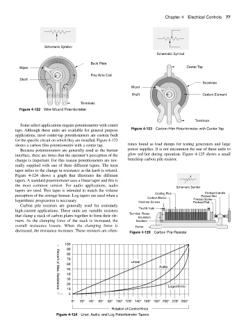
Some select applications require potentiometer with center
taps. Although these units are available for general purpose Figure 4-123 Carbon Film Potentiometer with Center Tap
applications, most center-tap potentiometers are custom built
for the specific circuit on which they are installed. Figure 4-123
shows a carbon film potentiometer with a center tap. times found as load dumps for testing generators and large
Because potentiometers are generally used as the human power supplies. It is not uncommon for one of these units to
interface, there are times that the operator’s perception of the glow red hot during operation. Figure 4-125 shows a small
change is important. For this reason potentiometers are nor- benchtop carbon pile resistor.
mally supplied with one of three different tapers. The term
taper refers to the change in resistance as the knob is rotated.
Figure 4-124 shows a graph that illustrates the different
tapers. A standard potentiometer uses a linear taper and this is
the most common version. For audio applications, audio
Schematic Symbol
tapers are used. This taper is intended to match the volume
Cooling Fins Preload Handle
perception of the average human. Log tapers are used when a Preload Nut
Carbon Blocks Preload Screw
logarithmic progression is necessary. Machine Screws Preload Pad
Carbon pile resistors are generally used for extremely
Thumb Nuts
high-current applications. These units are variable resistors
Terminal Plates
that clamp a stack of carbon plates together to form their ele-
Insulators
ment. As the clamping force of the stack is increased, the Insulator
overall resistance lowers. When the clamping force is Frame
decreased, the resistance increases. These resistors are often- Figure 4-125 Carbon Pile Resister
100
90
80
70
Linear
60
Audio
50
40
30
20
Logarithmic
10
Percent of Max. Resistance
0
0° 20° 40° 60° 80° 100° 120° 140° 160° 180° 200° 220° 260°
Rotation of Control Knob
Figure 4-124 Liner, Audio, and Log Potentiometer Tapers