
Page 117 - Electromechanical Devices and Components Illustrated Sourcebook
P. 117
Chapter 4 Electrical Controls 79
1 X
Common
Potentiometer
10 X
Jumper
Terminals
100 X
Variable
Output
Input
1K X
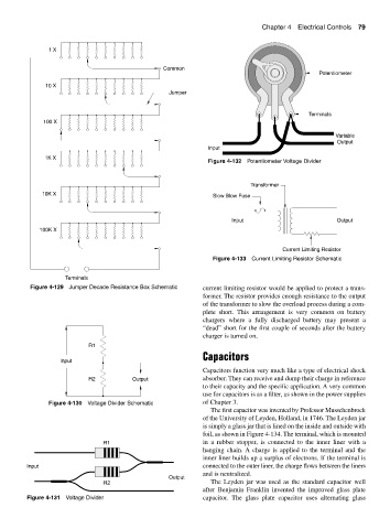
Figure 4-132 Potentiometer Voltage Divider
Transformer
10K X Slow Blow Fuse
Input Output
100K X
Current Limiting Resistor
Figure 4-133 Current Limiting Resistor Schematic
Terminals
Figure 4-129 Jumper Decade Resistance Box Schematic current limiting resistor would be applied to protect a trans-
former. The resistor provides enough resistance to the output
of the transformer to slow the overload process during a com-
plete short. This arrangement is very common on battery
chargers where a fully discharged battery may present a
“dead” short for the first couple of seconds after the battery
charger is turned on.
R1
Capacitors
Input
Capacitors function very much like a type of electrical shock
R2 Output absorber. They can receive and dump their charge in reference
to their capacity and the specific application. A very common
use for capacitors is as a filter, as shown in the power supplies
Figure 4-130 Voltage Divider Schematic of Chapter 3.
The first capacitor was invented by Professor Musschenbrock
of the University of Leyden, Holland, in 1746. The Leyden jar
is simply a glass jar that is lined on the inside and outside with
foil, as shown in Figure 4-134. The terminal, which is mounted
R1 in a rubber stopper, is connected to the inner liner with a
hanging chain. A charge is applied to the terminal and the
inner liner builds up a surplus of electrons. If the terminal is
Input connected to the outer liner, the charge flows between the liners
and is neutralized.
Output
R2 The Leyden jar was used as the standard capacitor well
after Benjamin Franklin invented the improved glass plate
Figure 4-131 Voltage Divider capacitor. The glass plate capacitor uses alternating glass