
Page 112 - Electromechanical Devices and Components Illustrated Sourcebook
P. 112
74 Electromechanical Devices & Components Illustrated Sourcebook
Terminal
Exposed Element
Schematic Symbol
Resistive Coil
Machine Screw
Ceramic Coating
Mounts
Thumb Nut
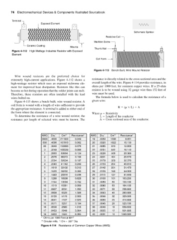
Figure 4-112 High-Wattage Industrial Resistor with Exposed
Element
Coil Form
Figure 4-113 Bench Built, Wire Wound Resister
Wire wound resistors are the preferred choice for
extremely high-current applications. Figure 4-112 shows a resistance is directly related to the cross sectional area and the
high-wattage resistor which uses an exposed nichrome ele- overall length of the wire. Figure 4-114 provides resistance, in
ment for improved heat dissipation. Resistors like this can ohms per 1000 feet, for common copper wires. If a 25-ohm
become so hot during operation that the solder joints can melt. resistor is to be wound using 32 gauge wire then 152 feet of
Therefore, these resistors are often installed with the lead wire must be used.
wires bolted on. The formula below is used to calculate the resistance of a
Figure 4-113 shows a bench built, wire wound resistor. A given wire:
coil form is wound with a length of wire sufficient to provide
R ( L) A
the appropriate resistance. A terminal is added to either end of
the form where the element is connected. Where Resistivity
To determine the resistance of a wire wound resistor, the L Length of the conductor
resistance per length of selected wire must be known. The A Cross sectional area of the conductor.
AWG Dia." Cm** Resistance* AWG Dia." Cm** Resistance*
0000 .4600 211600 0.049 19 .0359 1288 8.051
000 .4096 167810 0.062 20 .0320 1022 10.150
00 .3648 133080 0.078 21 .0285 810 12.800
0 .3248 105530 0.098 22 .0254 642 16.140
1 .2893 83694 0.124 23 .0226 509 20.360
2 .2576 66373 0.156 24 .0201 404 25.670
3 .2294 52634 0.197 25 .0179 320 32.370
4 .2043 41742 0.249 26 .0159 254 40.810
5 .1819 33102 0.313 27 .0142 201 51.470
6 .1620 26250 0.395 28 .0126 160 64.900
7 .1443 20816 0.498 29 .0113 127 81.830
8 .1289 16509 0.628 30 .0100 101 103.200
9 .1144 13094 0.792 31 .0089 80 130.100
10 .1019 10381 0.999 32 .0080 63 164.100
11 .0907 8234 1.260 33 .0071 50 206.900
12 .0808 6529 1.588 34 .0063 40 260.900
13 .0720 5178 2.003 35 .0056 32 329.000
14 .0641 4107 2.525 36 .0050 25 414.800
15 .0571 3257 3.184 37 .0045 20 523.100
16 .0508 2583 4.016 38 .0040 16 659.600
17 .0453 2048 5.064 39 .0035 12 831.800
18 .0403 1624 6.385 40 .0031 10 1049.000
* Ohms per 1000 Feet at 68°F
** Circular mills. 1 Cm = .001" Dia.
Figure 4-114 Resistance of Common Copper Wires (AWG)