
Page 109 - Electromechanical Devices and Components Illustrated Sourcebook
P. 109
Chapter 4 Electrical Controls 71
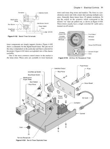
Contactor Switched Outlet stores and many drug stores and markets. The timer is a syn-
chronous motor unit with a timer dial carrying multiple actu-
ators. Generally these timers have 15 minute resolution. To
Multifunction trip the switch on the actuators which correspond to the
Relay desired “on” time are pulled out, as shown in Figure 4-104.
Auto/Manual Switch
Start Button These timers usually have a single switched AC outlet and a
4 5 6 manual on-off switch.
3 7 Power Switch
2 8
1 9 Fuse
Stop/Reset 11 10
Button
120 VAC
Actuators
(Shown Off) Time Pointer
11 12 1 2 3
Figure 4-102 Bench Timer Schematic Actuators 10 4 AM Scale
9 5
(Shown On)
8 6
PM Scale 7 24 Hour 7 Timer Dial
6 8
5 9
4 10
timer components are simply support electrics. Figure 4-102 3 2 1 12 11
Manual On/Off Switch
shows a schematic for the digital bench timer. The pin-out of
ON
the relay is dependent on the particular unit that is selected for
OFF
the project. Figure 4-103 shows an exploded view of the chassis
Switched Output
assembly. Case
One of the most common control timers in the market is
the lamp timer. These units are available in most hardware Figure 4-104 24-Hour AC Receptacle Timer
Fuse Holder
Switched Output Fuse
Auto/Manual Switch Rear Panel
Stop/Reset Button
Multifunction
Digital Relay
Start Button
Strain Relief
Front Panel
Power
Switch AC Cord
START
Contactor
STOP/RESET
AUTO/MANUAL
POWER
REMOTE
Cabinet
Foot
Remote Receptacle
Figure 4-103 Bench Timer Exploded View