
Page 107 - Electromechanical Devices and Components Illustrated Sourcebook
P. 107
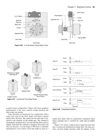
Chapter 4  Electrical Controls 69


                                                                                           Limit Switch
                                                                 Panel Mount
                  Limit Switch
                                                                                           Frame
                                                            Operator Dial
                    Stop Pin                                                                Stop Pin
                    Trip Cam
                  Stop Cam              T  0
                                       SE      10
                     Frame
                                      60         20

                                        50      30
                  Operator Dial             40
                                                                                            Spring Motor
                   Cam Disk                                             Cam Disk

                                        Front View                                Side View
                  Figure 4-96 0- to 60-Second Spring Return Timer


                                                                                  On
                                                                           Power
                                                                                  Off
                                                              Delay On            On     Delay Off
                                                                           Relay
                                                                                  Off
                                                                                  On
                                                                           Power
                                                              Delay Off           Off
                                                                                  On
                                                                           Relay
          Multifunction Digital                                                   Off    Delay On
            Panel Mount
                                        Multifunction                      Power  On
                                                              Repeat Cycle        Off
                                                                                           On Time
                                                                                  On
                                                                           Relay
                                                                                  Off
                                                                                             Off Time
                                                                                  On
                                                                           Power
                                                              Power Off Delay     Off
                           Repeat Cycle                                                   Off Delay
                                                                                  On
                                                                           Relay
                                                                                  Off
                                        Single Function Analog
          Single Function                   Panel Mount
                                                                                  On
          Figure 4-97 Commercial Time Delay Relays                         Power
                                                              Delay On-Off        Off      On Time
                                                                                  On
                                                                           Relay
                                                                                  Off
                                                                                      Delay On
        as panel mount configurations. Figure 4-98 shows graphical
                                                              Figure 4-98 Timing Relay Functions
        representation of the most common timing functions that
        these relays can provide.
           Some lab timers are designed to use a ratchet drive with a
        repeat cycle relay for the clock. Figure 4-99 shows a typical
        ratchet drive lab timer. The ratchet has 60 teeth and is con-  ratchet drive timer. Like its synchronous counterpart, these
        nected to the solenoid via the ratchet paw. The solenoid is  timers generally have a switched AC outlet and an audible
        momentarily energized once a second until the limit switch is  alarm.
        tripped. Each time the solenoid is energized, the pointer and  Figure 4-101 shows a high-accuracy digital lab timer that
        trip cam advances 1 second. Figure 4-100 shows a schematic  uses a commercial multifunction timing relay. The relay pro-
        representation of the control circuit that might be used on a  vides excellent timing functions while the balance of the