
Page 102 - Electromechanical Devices and Components Illustrated Sourcebook
P. 102
64 Electromechanical Devices & Components Illustrated Sourcebook
Limit Switches Solenoid
Lever Arm Solenoid Terminals
Diaphragm Spring Solenoid Spring
Delay Adjustment
Diaphragm Housing Frame
Figure 4-80 Commercial Relay with Pneumatic Time Delay
Common
Switched Terminals
Switched Wiper
5 6 7
Switched Contacts 3 8
2 9
1 10
Bridge Link
Dash Pot
Damping
Coils
Adjustment
Pivot
Control Wiper
Control Contacts Flexible Connection
Base
Control Terminals
Common
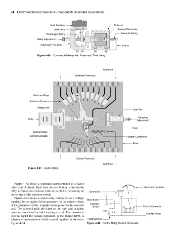
Figure 4-81 Sector Relay
Figure 4-82 shows a schematic representation of a sector
relay control circuit. Each time the start button is pressed the Switched Contacts
relay advances one position either up or down, depending on Solenoids
the setting of the direction switch.
Figure 4-83 shows a sector relay configured as a voltage
Start Button
regulator for an engine-driven generator. As the output voltage
Direction
of the generator climbs, it applies more power to the solenoid
Switch Control Contacts
coil. The solenoid pulls the wiper to the right and switches
NC
more resistors into the field winding circuit. The rheostat is
Control Power
used to adjust the voltage regulation to the engine RPM. A
schematic representation of this type of regulator is shown in Holding Relay
Figure 4-84. Figure 4-82 Sector Relay Control Schematic