Page 96 - Electromechanical Devices and Components Illustrated Sourcebook
P. 96

58 Electromechanical Devices & Components Illustrated Sourcebook


                                                  Chassis Ground                          Run/Off
                                                                                          Switch
                                                  Output Fuse
                                           Input Fuses
                                                                                            Start
                                                                                            Button


                                  Control
                                Transformer                                                Emergency
                                                               120 VAC                       Stop

                               Enclosure
                                                     240/480 VAC
                              Coil Terminals                                           Sensor Loop


                                                      MOTOR    RESET
                                                     STARTER
                                                     120 VAC COIL
                                                                                       Motor
                         Power
                     (240/480 VAC)
                                                                 Heater Set
                                             Contactor
                     Figure 4-67 Commercial Motor Controller with Sensor Loop


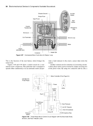
        This is the function of the start button, which bridges the  vides a fault indicator in the event a sensor shuts down the
        sensor loop.                                          system.
           Figures 4-68 and 4-69 show a control circuit for a com-  Another common use for contactors is in reversing circuits.
        mercial screw compressor. This particular unit is designed to  A three-phase motor can be reversed by simply reversing two
        operate either continuously or in an automatic mode and pro-  of the power wires. By using two contactors side-by-side, a


                                                                 Motor Controller (From Page 9-5)
                             240/480 VAC
                             Three Phase

                                                  C           L      Power
                                                                                 M

                                                                               Motor
                                                                   Control
                                                                    Relay
                                                    Fault  L


                                               On/Off/Auto
                                                 Switch                         Over Pressure
                                                                                Low Oil Pressure

                                                                                 Over Temperature
                                                             T
                                                             Delay Off
                                 Pressure                                       Emergency Stop
                                  Switch
                             Figure 4-68 Three-Phase Motor Control Circuit Diagram with Run/Automatic Mode,
                             Sensors, and Fault Indicator Lamp
   91   92   93   94   95   96   97   98   99   100   101