
Page 80 - Electromechanical Devices and Components Illustrated Sourcebook
P. 80
42 Electromechanical Devices & Components Illustrated Sourcebook
Button Button
Mount Nuts
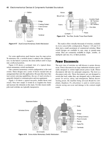
Insulator Stack
Body Bridge NC Terminal
Common
Floating Contact Frame NO Terminal
Fixed Contact Pole Sets
Spring
Rivets
Contacts
Terminal
Figure 4-19 Two-Pole, Double Throw Reed Switch
Guide Pin
Figure 4-17 Dual-Contact Momentary Switch Mechanism The market offers virtually thousands of switches, available
in every conceivable configuration. Figures 4-20 and 4-21
show just a small assortment of commercial switches. Most
switch designs are available in cam, snap, or pseudo-snap
action. They are commonly available in single-, double-, or
multipole and one, two, or three position.
For some applications push buttons must be snap action.
To minimize size, a resilient dome is added to the configura-
tion. As the button is pressed, the dome deflects until it snaps Power Disconnects
into a deflected position.
Figure 4-18 shows a sectional view of a typical dome- The next class of switches we will discuss is power discon-
action momentary switch mechanism. nects. Power disconnects are large industrial switches specif-
One common momentary switch configuration is the reed ically designed to switch high-current power feeds. Power
switch. These designs use a series of leaves stacked into an disconnects fall into two principal categories. The first is a
arrangement that suits the application. Because they have lim- disconnect-only-role. These disconnects are not designed to
ited current carrying capabilities, the use of reed switches is switch the load, rather they are designed only to disconnect
generally limited to communication and test equipment. power for service, safety, and emergencies. Before discon-
Figure 4-19 shows a typical two-pole, double throw reed necting power, the machine being serviced should be com-
switch. Note how simple it would be to lengthen the frame pletely shutdown. If a disconnect is used to switch power,
and increase the elements in the stack. For this reason multi- extreme arcing can occur and damage to the contacts might
pole reed switches are typically inexpensive. result.
Button
Depressed Button
Body
Deflected Dome Dome
Bridge
Floating Contacts
Fixed Contacts
Spring
Guide Pin
Terminals
On (Closed) Off (Open)
Figure 4-18 Dome-Action Momentary Switch Mechanism