
Page 69 - Electromechanical Devices and Components Illustrated Sourcebook
P. 69
Chapter 3 Power Sources 31
Step-Down Transformer Step-Down
Secondary
Primary Transformer
Diodes
−
Filter Capacitor
Binding Post
Pulsed-DC Output
AC Input (Positive Side Only)
+
Single Diode Rubber Foot
Figure 3-46 Half-Wave DC Power Supply Schematic
Base
AC Input
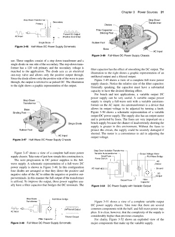
Figure 3-49 Full-Wave DC Power Supply Chassis
use. These supplies consist of a step down transformer and a
single diode on one side of the secondary. The step-down trans-
former has a 120 volt primary and the secondary voltage is
filter capacitor has the effect of smoothing the DC output. The
matched to the application. The diode acts as an electrical
illustration to the right shows a graphic representation of an
one-way valve and allows only the positive output through.
unfiltered output and a filtered output.
Since the diode allows only the positive side of the wave to pass
Figure 3-49 shows a view of a complete full-wave power
through, the output is referred to as pulsed DC. The illustration
supply chassis. Notice the relative size of the filter capacitor.
to the right shows a graphic representation of the output.
Generally speaking, the capacitor must have a substantial
capacity to have the desired filtering effect.
For bench and test applications, a variable output DC
power supply can be very useful. A variable output power
Step-Down supply is simply a full-wave unit with a variable autotrans-
Transformer
former on the AC input. An autotransformer is a device that
allows its output voltage to be adjusted by turning a knob.
Base
Binding Post Figure 3-50 shows a schematic representation of a variable
output DC power supply. The supply also has an output meter
and is protected by fuses. The fuses are very important on a
bench supply because the chance of inadvertently shorting the
Single Diode
supply is greater in this environment. Without the fuses to
Rubber Foot protect the circuit, the supply could be severely damaged if
shorted. The meter is a convenience to aid in adjusting the
AC Input
output voltage.
Figure 3-47 Half-Wave DC Power Supply Chassis
Step-Down Isolation Transformer
Figure 3-47 shows a view of a complete half-wave power Variable Autotransformer Output Voltage Meter
supply chassis. Take note of just how simple this construction is. Input Fuse Full-Wave Bridge
Power Switch
The next progression in DC power supplies is the full-
AC
wave supply. A schematic representation of a full-wave DC Output
power supply is shown in Figure 3-48. In this configuration
AC Input Ground
four diodes are arranged so that they direct the positive and
−
negative sides of the AC to either the negative or positive out- − DC
+ + Output
put terminals. In this manner the full output of the transformer
Output Fuse Filter
is utilized. To improve the output, these power supplies usu- Capacitor
ally have a filter capacitor that bridges the DC terminals. The Figure 3-50 DC Power Supply with Variable Output
Step-Down Full-Wave Bridge
Transformer Figure 3-51 shows a view of a complete variable output
DC power supply chassis. Take note that there are several
−
− UnFiltered Output common components with the half- and full-wave power sup-
AC Input + plies. It is clear, however, that the complexity of the supply is
+
considerably higher than previous examples.
Filtered Output
Filter Capacitor For clarity, Figure 3-52 shows an exploded view of the
Figure 3-48 Full-Wave DC Power Supply Schematic major components that make up the variable supply.