
Page 56 - Electromechanical Devices and Components Illustrated Sourcebook
P. 56
18 Electromechanical Devices & Components Illustrated Sourcebook
When dealing with electromechanical equipment, it is neces- and points below the line being negative volts, with electrons
sary to have a clear understanding of the various types of flow in the opposite direction. In the United States, AC power
electrical power that are at our disposal. There are two basic is delivered at 60 cycles per second, which means that a full
1
types of electrical power, direct current (DC) and alternating AC cycle is / 60 of a second long. The illustration shows that
1
current (AC). for the first half of the cycle ( / 120 sec) the polarity is positive
1
and for the second half of the cycle ( / 120 sec) the polarity
reverses and is negative.
Direct Current (DC) Alternating current has a number of significant attributes
that will be discussed further in the following chapters of the
Direct current is electrical power which maintains a flow of book.
electrons in one direction only. The basic circuit shown in For most applications there are four standard AC voltages.
Figure 3-1 illustrates DC. Electrons flow from the negative These are 24, 120, 240, and 480 volts. AC voltage of 24 volts
terminal on the battery, through the light bulb, and back to the doesn’t represent a significant shock hazard, so it is preferred
positive terminal. Most devices that use batteries operate as a control voltage in most commercial and industrial equip-
using DC. Your automobile, calculator, flash light, transistor ments. It is also used as the primary voltage for model trains
radio, camera, and wall clock all operate on DC. and slot cars. These toys have exposed terminals and safety
considerations dictate that nonlethal voltages are used.
AC voltage of 120 volts is commonly found at the recepta-
+ −
cles inside our houses. Most small appliances in the United
Electron Flow States operate on 120 volts. Additionally, 120 volts is a com-
mon control voltage in industrial equipment where it is used
primarily to limit the current and, consequently, the wire size
that is used for the circuit of equipment.
Voltage of 240 volts is typically supplied to homes. This
voltage can be reduced to 120 volts for use in the home’s out-
lets. Major appliances and larger motors will generally oper-
ate on 240 volts. The higher voltage provides the same power
with lower current and, therefore, smaller wire. It should be
noted that 240 volts represents a significant shock hazard.
Severe injury or death can occur if this voltage is handled
Battery Light Bulb
improperly. Before working with any 240-volt circuit, be cer-
Figure 3-1 Direct Current Electron Flow tain that the power is turned off and locked out.
Voltage of 480 volts is generally reserved for industrial
applications. It carries the voltage/current advantage a step
Alternating Current (AC) further. Generally speaking, motors over 25 horsepower,
induction furnaces, arc welders, and overhead cranes will be
The second type of electrical power is AC. The way this type operating on 480 volts. Even more than 240 volts, 480 volts,
of power works is not so intuitive as DC power and can be a can be very dangerous to work with. Severe injury or death
little difficult to understand when discussing the various ways can occur if this voltage is handled improperly. Only properly
it is applied. trained electricians should work with 480-volt circuits. As
Alternating current is the type of power that is delivered to with other circuits the power should be disconnected and
homes and business. It is referred to as AC because its polar- locked out before working with 480 volt equipment.
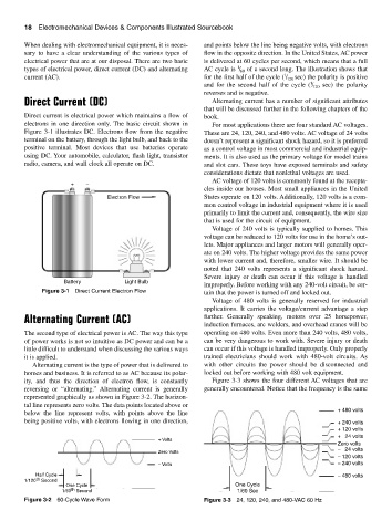
ity, and thus the direction of electron flow, is constantly Figure 3-3 shows the four different AC voltages that are
reversing or “alternating.” Alternating current is generally generally encountered. Notice that the frequency is the same
represented graphically as shown in Figure 3-2. The horizon-
tal line represents zero volts. The data points located above or
+ 480 volts
below the line represent volts, with points above the line
being positive volts, with electrons flowing in one direction, + 240 volts
+ 120 volts
+ 24 volts
+ Volts
Zero volts
− 24 volts
Zero Volts
− 120 volts
− Volts − 240 volts
Half Cycle − 480 volts
1/120 th Second
One Cycle One Cycle
1/60 th Second 1/60 Sec
Figure 3-2 60-Cycle Wave Form Figure 3-3 24, 120, 240, and 480-VAC 60 Hz