
Page 141 - Embedded Microprocessor Systems Real World Design
P. 141
A
SETPBFUESSEO
OVERALL STATE DIAGRAM
POWERFAIL
RESET MODE
C
NORMAL TIME MODE STATE DIAGRAM
SET MODE SET MODE
PRESSED
WATER LEML OK,
1 OFF TIMING
FVMP OFF PUMP OFF
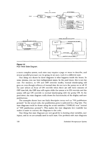
Figure 4.2
Pool Timer State Diagram.
a more complex system, each state may require a page or more to describe, and
several parallel processes can be going on at once, each in a different state.
One thing not shown by these diagrams is what happens inside the boxes. In
some systems, you can have independent states. In the pool timer, this is not the
case. For instance, in ON and OFF override modes, normal timekeeping still
goes on even though rollovers of normal time do not turn the pump on or off. If
the user selects an hour of ON override when there are still three minutes of
OFF time left, the OFF time will expire while the system is in ON override and the
system will exit ON override to normal timekeeping with the pump ON. In the
pool timer, the state diagram really shows the functionality of the display and user
pushbuttons.
The examples shown here use fairly descriptive terms such as “ON pushbutton
pressed.” In the actual code, the pushbutton press is indicated by a flag byte. The
state diagrams could be drawn using the actual variables (“ONFLAG true” instead
of “ON pushbutton pressed”). This makes the state diagrams less readable but
makes it easier to connect the diagrams to the code.
One thing that state diagrams are very good for is showing what variables, user
inputs, and so on are actually used in each state. One problem with state diagrams
122 Embedded Microprocessor System