
Page 218 - Embedded Microprocessor Systems Real World Design
P. 218
ITEMS IN-HOPPER, AWAITING FEED
I
FEED MECHANISM
SENSOR 1 !
DIRECTION OF MOTION -D
I
MOTOR
0 Q COMMANDS FROM
HIGHER LEVEL
EN C 0 DER MICROCONTROLLER CONTROLLER
SENSORS
START
STOP
FEED RATE
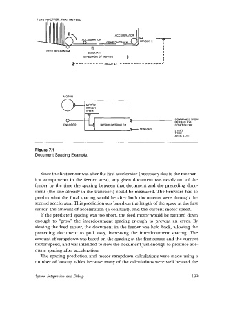
Figure 7.1
Document Spacing Example.
Since the first sensor was after the first accelerator (necessary due to the mechan-
ical components in the feeder area), any given document was nearly out of the
feeder by the time the spacing between that document and the preceding docu-
ment (the one already in the transport) could be measured. The firmware had to
predict what the final spacing would be after both documents were through the
second accelerator. This prediction was based on the length of the space at the first
sensor, the amount of acceleration (a constant), and the current motor speed.
If the predicted spacing was too short, the feed motor would be ramped down
enough to “grow” the interdocument spacing enough to prevent an error. By
slowing the feed motor, the document in the feeder was held back, allowing the
preceding document to pull away, increasing the interdocument spacing. The
amount of rampdown was based on the spacing at the first sensor and the current
motor speed, and was intended to slow the document just enough to produce ade-
quate spacing after acceleration.
The spacing prediction and motor rampdown calculations were made using a
number of lookup tables because many of the calculations were well beyond the
System Integration and Debug 199