
Page 322 - Academic Press Encyclopedia of Physical Science and Technology 3rd Chemical Engineering
P. 322
P1: GSY/GSR/GLT P2: GLM Final Pages
Encyclopedia of Physical Science and Technology EN007E-968 June 30, 2001 17:35
368 High-Pressure Synthesis (Chemistry)
FIGURE 1 Cross section of simple piston and cylinder appara-
tus at high pressure. Original shape indicated by dashed lines.
Distortions due to pressure are exaggerated.
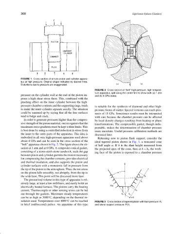
FIGURE 2 Cross section of “belt” high-pressure, high tempera-
ture apparatus, split along the center line to show both (a) 1 atm
pressure on the cylinder wall at the end of the piston im- and (b) 6 GPa states.
poses a high shear stress there. This, combined with the
pinching effect on the inner cylinder between the high-
pressure-chamber contents and the supporting rings, tends is suitable for the synthesis of diamond and other high-
to make the inner cylinder separate axially. The situation pressure forms of matter. Special versions can reach pres-
could be summed up by saying that all the free surfaces sures of 15 GPa. Sometimes results must be interpreted
tend to bulge and crack. with care because the chamber pressure can be affected
In order to generate pressures higher than the compres- by local density changes resulting from heating or phase
sive strength of the piston material, one recognizes that the transformations. The compressible gasket, though indis-
maximum stress gradients must be kept within limits. This pensable, makes the determination of chamber pressure
is best done by using a controlled reduction in stress from more uncertain. Useful pressure calibration methods are
the inner to the outer parts of the apparatus. This idea is discussed later.
embodied in all very high-pressure apparatus used above Returning now to piston flank support, consider the
about 4 GPa and can be seen in the cross section of the ideal tapered piston shown in Fig. 3, a truncated cone
“belt” apparatus shown in Fig. 2. The figure shows the sit- of half angle α.If h is the slant height measured from
uation at 1 atm and at 6 GPa. A composite conical gasket, the projected apex of the cone, then at h = h 0 the work-
consisting of a stone–steel–stone sandwich, seals the gap ing face of the piston is exposed to a chamber pressure
between piston and cylinder, permits the motion necessary
for compressing the chamber contents, provides electrical
and thermal insulation, and also supports the piston and
cylinder surfaces with a monotonic fall in pressure from
the tip of the piston to the atmosphere. Thus, the net stress
on the piston falls smoothly, not abruptly, from the tip to
the wide base. This point will be discussed more later.
The pressurized volume in this type of apparatus is rel-
atively large, at least a few milliliters, and easily holds an
electrically heated furnace. The pistons carry the heating
current. Thermocouple or other sensing wires can be led
out through the gaskets. Maximum steady temperatures
◦
can be as high as 3000 C, depending on the thermal in-
sulation used. Temperatures over 4000 C can be reached
◦
FIGURE 3 Cross section of tapered piston with face pressure P 0
in brief (millisecond) pulses. An apparatus of this type and lateral support pressure P(h).