
Page 302 - Academic Press Encyclopedia of Physical Science and Technology 3rd Polymer
P. 302
P1: GQT/MBQ P2: GPJ Final Pages
Encyclopedia of Physical Science and Technology EN014C-660 July 28, 2001 17:14
240 Rheology of Polymeric Liquids
FIGURE 4 Schematic describing the velocity profile of a liquid
flowing through a cylindrical tube.
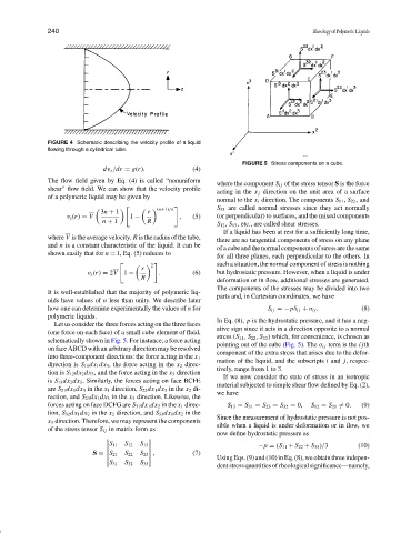
FIGURE 5 Stress components on a cube.
dv z /dr = g(r). (4)
The flow field given by Eq. (4) is called “nonuniform
where the component S ij of the stress tensor S is the force
shear”flow field. We can show that the velocity profile
acting in the x j direction on the unit area of a surface
of a polymeric liquid may be given by
normal to the x i direction. The components S 11 , S 22 , and
S 33 are called normal stresses since they act normally
(n+1)/n
3n + 1 r
v z (r) = V 1 − , (5) (or perpendicular) to surfaces, and the mixed components
n + 1 R
S 12 , S 13 , etc., are called shear stresses.
If a liquid has been at rest for a sufficiently long time,
where V is the average velocity, R is the radius of the tube,
there are no tangential components of stress on any plane
and n is a constant characteristic of the liquid. It can be
of a cube and the normal components of stress are the same
shown easily that for n = 1, Eq. (5) reduces to
for all three planes, each perpendicular to the others. In
such a situation, the normal component of stress is nothing
2
r
v z (r) = 2V 1 − . (6) but hydrostatic pressure. However, when a liquid is under
R deformation or in flow, additional stresses are generated.
The components of the stresses may be divided into two
It is well-established that the majority of polymeric liq-
parts and, in Cartesian coordinates, we have
uids have values of n less than unity. We describe later
how one can determine experimentally the values of n for S ij =−pδ ij + σ ij . (8)
polymeric liquids.
In Eq. (8), p is the hydrostatic pressure, and it has a neg-
Let us consider the three forces acting on the three faces
ative sign since it acts in a direction opposite to a normal
(one force on each face) of a small cube element of fluid,
stress (S 11 , S 22 , S 33 ) which, for convenience, is chosen as
schematically shown in Fig. 5. For instance, a force acting
pointing out of the cube (Fig. 5). The σ ij term is the ijth
on face ABCD with an arbitrary direction may be resolved
component of the extra stress that arises due to the defor-
into three-component directions: the force acting in the x 1
mation of the liquid, and the subscripts i and j, respec-
direction is S 11 dx 1 dx 3 , the force acting in the x 2 direc-
tively, range from 1 to 3.
tion is S 12 dx 2 dx 3 , and the force acting in the x 3 direction
If we now consider the state of stress in an isotropic
is S 13 dx 2 dx 3 . Similarly, the forces acting on face BCFE
material subjected to simple shear flow defined by Eq. (2),
are S 21 dx 1 dx 3 in the x 1 direction, S 22 dx 1 dx 3 in the x 2 di-
we have
rection, and S 23 dx 1 dx 3 in the x 3 direction. Likewise, the
forces acting on face DCFG are S 31 dx 1 dx 2 in the x 1 direc- S 13 = S 31 = S 23 = S 32 = 0, S 12 = S 21 = 0. (9)
tion, S 32 dx 1 dx 2 in the x 2 direction, and S 33 dx 1 dx 2 in the
Since the measurement of hydrostatic pressure is not pos-
x 3 direction. Therefore, we may represent the components
sible when a liquid is under deformation or in flow, we
of the stress tensor S ij in matrix form as
now define hydrostatic pressure as
S
11 S 12 S 13 −p = (S 11 + S 22 + S 33 )/3 (10)
S = S 21 S 22 S 23 , (7)
Using Eqs. (9) and (10) in Eq. (8), we obtain three indepen-
S 31 S 32 S 33
dentstressquantitiesofrheologicalsignificance—namely,