
Page 28 - Subyek Encyclopedia - Encyclopedia of Separation Science
P. 28
Sepsci*11*TSK*Venkatachala=BG
I / CENTRIFUGATION 23
The types of separation to be discussed focus on the to separating particles of similar density according
separation of solids from liquid media using any of to size (classiRcation), an approximate order of mag-
the recovery modes described above. Discussion of nitude difference in mass between the particles is
simpler batch-mode operation is emphasized for sim- needed for differential sedimentation to be effective.
plicity. Three primary types of centrifugal separations The main disadvantage of separating a homogenate
are discussed: differential sedimentation, density in batch mode is that the centrifugal Reld required to
gradient and Rltration, with density gradient being pellet the larger or denser particles that are initially
further divided into rate-zonal and isopycnic (in nearer the axis of rotation is capable of pelleting
isopycnic separations, particles sediment until they smaller or lighter particles initially closer to the outer
attain a position in the gradient at which the medium wall (Figure 3). Product purity or recovery may be
density is equal to their own). improved by either recentrifuging the supernatant to
obtain more pellet, or by resuspending the pellet and
recentrifuging to obtain higher purity. When purity
Differential Sedimentation
is the primary concern, this approach can still be
As previously shown by the equations describing sedi- used as a preparatory step to provide an enriched
mentation (eqns [13] and [14]), larger and/or denser fraction for subsequent puriRcation. However,
particles will sediment more rapidly in a centrifugal a more efRcient one-step approach is to layer the
force Reld and will thus pellet onto the outer wall of sample mixture on top of the preloaded medium.
the rotor faster than smaller or lighter particles. Most Stopping the run before the lighter or smaller con-
applications are based on this difference in be- taminant particles reach the rotor wall allows them to
haviour, referred to as differential sedimentation be decanted with the supernatant. An alternative is
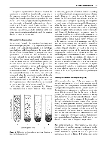
or pelleting. In a simple batch-mode pelleting separ- to use a continuous-feed rotor in which the sample
ation, a sample mixture called the homogenate (im- mixture is introduced near the axis of rotation and
miscible liquids or solid suspensions) is placed into the supernatant, containing the smaller or lighter
a centrifuge container or rotor, and separated into unsedimented particles, is continuously discharged.
two fractions as depicted in Figure 3. The un- A more efRcient approach is to layer or feed the
sedimented material is termed the supernatant and sample to the top of a preloaded density gradient (see
the sedimented material is the pellet. This approach below).
works well when the objective is to pellet all the solid
particles or to clarify the liquid. Such separations are Density Gradient Centrifugation (DGC)
also commonly used in the laboratory for ‘quick and
dirty’ separations or where the objective is to enrich DGC, developed in the 1950s, also relies on dif-
or clarify materials for subsequent analysis. ferential sedimentation behaviour to separate sample
Obtaining high purity separations by differen- components, but compensates for some of the disad-
tial sedimentation is more difRcult. With respect vantages of homogeneous media and also allows for
the simultaneous separation of multicomponent mix-
tures. This is accomplished by the use of a density
gradient, i.e. a liquid medium that increases in density
from the layers nearest the axis of rotation to those
farthest away. As will be discussed, this is achieved
through variation in the concentration of an aqueous
solute, or other gradient material, across the rotor.
With minimal precautions, density gradients are sur-
prisingly stable for extended periods, even with the
rotor stopped. DGC separations are more extensively
used for smaller-scale research applications in con-
trast to large-scale pelleting separations that are more
common to industrial applications. DGC may be con-
ducted as either rate or isopycnic separations.
Rate-zonal separations This technique, also called
classiRcation, is used to separate particles of similar
density according to size. For batch separations, the
Figure 3 Differential sedimentation or pelleting. (Courtesy of sample mixture is layered on top of a preloaded
Beckman Instruments, Inc.) medium, as shown in Figure 4. During a rate-zonal