
Page 148 - Engineered Interfaces in Fiber Reinforced Composites
P. 148
Chapter 4. Micromechanics of stress transfer 131
z
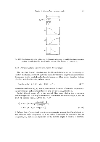
Fig. 4.22. Distributions of (a) fiber axial stress, 6, matrix axial stress, uk, and (c) interface shear stress.
(b)
T,, along the embedded fiber length in fiber pull-out. After Zhou et al. (1992a, b. c).
4.3.3. Interface debond criterion and partial debond stress
The interface debond criterion used in this analysis is based on the concept of
fracture mechanics. Substituting the solutions for the three major stress components
determined in the bonded and debonded regions, a fiber-matrix interface debond
criterion is derived for the pull-out test as
where the coefficients Bl, CI and D1 are complex functions of material properties of
the constituents and geometric factors, and are given in Appendix A.
Partial debond stress, a:, is the applied fiber stress during the progressive
debonding process that may be written as a function of the debond length, e, and the
crack tip debond stress, at, from Eq. (4.89)
o[exp(M) - I]
0: = IJI + (8 - op)
1 + o[exp(AC) - I]
M + (a - op)[l - exp(-JJ)l . (4.100)
It follows that o: consists of two stress components: a crack tip debond stress, ok,
and a friction stress component. 0e is not only a function of the interfacial fracture
toughness, Gi,, but is also dependent on the debond length, t, relative to the total