
Page 145 - Engineered Interfaces in Fiber Reinforced Composites
P. 145
128 Engineered interfaces im fiber reimforred composites
(1991) analyzed the effect of asperity pressure in the fiber pull-out and push-out
tests. The asperity interactions have also been modeled based on the classical
Hertzian contact law, leading to a sinusoidal modulation of the sliding stress (Carter
et al., 1991). Mackin et al. (1992a) also proposed a fractal model to incorporate the
asperity effects in the push-out loading geometry. In addition, rigorous fracture
mechanics analyses are presented by Liu et al. (1994a, b, 1995) for fiber pull-out and
push-out using a Fourier series representation of the fiber roughness effect. It has
been emphasized (Keran and Parthasarathy, 1991; Mackin et al., 1992a) that a
proper asperity wear mechanism must be introduced to explain the variation of the
fiber reseating behavior with sliding distance. This is viewed as gradual degradation
of the interface (frictional) properties due to the cyclic sliding in fatigue.
4.3.2. Solutions .for stress distributions
Much of the analysis to be presented in the following sections will encompass
what has been reported in recent publications (Kim et al., 1991, 1992, 1993a, b,
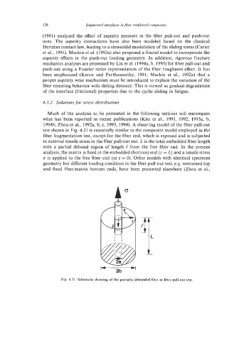
1994b; Zhou et al., 1992a, b, c, 1993, 1994). A shear-lag model of the fiber pull-out
test shown in Fig. 4.21 is essentially similar to the composite model employed in the
fiber fragmentation test, except for the fiber end, which is exposed and is subjected
to external tensile stress in the fiber pull-out test. L is the total embedded fiber length
with a partial debond region of length e from the free fiber end. In the present
analysis, the matrix is fixed at the embedded (bottom) end (z = L) and a tensile stress
cr is applied to the free fiber end (at z = 0). Other models with identical specimen
geometry but different loading condition in the fiber pull-out test, e.g. restrained top
and fixed fiber/matrix bottom ends, have been presented elsewhere (Zhou et al.,
Y
2b
Fig. 4.21. Schematic drawing of the partially debonded fiber in fiber pull-out test.