
Page 140 - Engineered Interfaces in Fiber Reinforced Composites
P. 140
Chapter 4. Micromechanics of stress transfer 123
-1
E
E
Y
-I
Eu
s
rn
C
a - Increasing On = 6,8,10 GPa
C :{I I I #
c
E
P
t
: n * n
t
LL
"0 I 0.02 ' 0.04 ' 0.k 0
Applied strain E
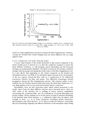
Fig. 4.18. Variation of mean fiber fragment length, 2L, as a function of applied strain, E, predicted in the
fully debonded interface model for constant fiber tensile strengths CTTS = 6.0, 8 and 10 GPa. After
Kim et al. (1993b).
results in a high applied strain required to initiate the fiber fragmentation. However,
varying the constant fiber tensile strength does not much influence (2L) at a high
applied strain.
4.2.4.4. Comparisons with earlier shear-lag models
A major improvement of the models presented in this section compared to the
earlier models given in Section 4.2.2 is that the conditions required to satisfy the
three different interfaces, i.e. full bonding, partial debonding and full frictional
bonding, are systematically identified. This gives an idea how the interface condition
changes with increasing load during the whole course of the fiber fragmentation test.
It is also shown that depending on the relative properties at the bonded and
debonded interfaces, the IFSS at the debonded region increases from the boundary
of the two regions toward the fiber ends as a consequence of the differential
contraction between the fiber and matrix. This effectively discourages debond
propagation during the fiber fragmentation process. This response makes it most
unlikely that the interface becomes debonded along the whole fiber length even at a
very high applied strain in most practical polymer matrix composites.
Nevertheless, there are also important issues which remain unresolved in this
model. Apart from the three different interface states discussed above, there are
other states of the interface due to yielding of matrix material immediately
surrounding the cylindrical fiber, and the combination of partial debonding and
partial yielding. Plastic yielding occurs in the matrix instead of interface debonding
if the interface shear bond strength, Tb, is sufficiently higher than the matrix yield
strength in shear, z,,, as in some composites containing ductile thermosets/
thermoplastics and metal matrices. To be able to model this behavior analytically
the exact knowledge regarding the effective thickness of the interphase region being