
Page 136 - Engineered Interfaces in Fiber Reinforced Composites
P. 136
Chapter 4. Micromechania of stress transfer I19
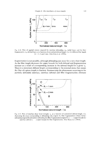
Fig. 4.14. Plots of applied stresses required for interface debonding, fJod (solid lines). and for fiber
fragmentation, u,f (dotted lines), as a function of normalized debond length, [/a, for different fiber length
2L = 1, 2 and 4 mm. After Kim et al. (1993b).
fragmentation is not possible, although debonding can occur for a very short length.
As the fiber length decreases the upper bounds for both debond and fragmentation
increase as a result of corresponding increase in the debond length for a given Zb.
There is a maximum debond length corresponding to the external stress that causes
the fiber of a given length to fracture. Summarizing the phenomena occurring in the
partially debonded interface, interface debond and fiber fragmentation alternate
t
r
Normalized debond length 4 /a
Fig. 4.15. Plots of interface shear bond strength, Zb, as a function of normalized debond length, [/a,
illustrating the areas corresponding to debonding only (region A), fiber fragmentation without further
debonding (region B) and neither debonding nor fiber fragmentation (region C): (-) upper bounds for
interface debond; (---) upper bounds for fiber fragmentation. After Kim et al. (1993b).