
Page 131 - Engineered Interfaces in Fiber Reinforced Composites
P. 131
114 Engineered interfaces in fiber reinforced composites
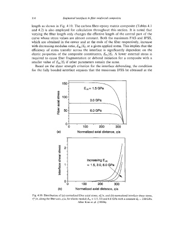
length as shown in Fig. 4.10. The carbon fiber-epoxy matrix composite (Tables 4.1
and 4.2) is also employed for calculation throughout this section. It is noted that
varying the fiber length only changes the effective length of the central part of the
curve whose stress values are almost constant. Both the maximum FAS and IFSS,
which are obtained in the center and at the ends of the fiber respectively, increase
with decreasing modulus ratio, E,/&, at a given applied stress. This implies that the
efficiency of stress transfer across the interface is significantly dependent on the
elastic properties of the composite constituents, E,/Ef. A lower external stress is
required to cause fiber fragmentation or debond initiation for a composite with a
smaller value of E,/Ef if other parameters remain the same.
Based on the shear strength criterion for the interface debonding, the condition
for the fully bonded interface requires that the maximum IFSS be obtained at the
150-
v)
100:
([I 3.0 GPa
'8
5
n 50: 6.0 GPa
LI
. u
0 1 00 200 300
(a) Normalized axial distance, z/a
2-
1- = 1.5,3.0,6.0 GPa
(b) Normalized axial distance, da
Fig. 4.10. Distribution of (a) normalized fiber axial stress, ofla, and (b) normalized interface shear stress,
Q/a, along the fiber axis, z/a, for elastic moduli E, = 1.5,3.0 and 6.0 GPa with a constant Ef = 230 GPa.
After Kim et al. (1993b).