
Page 139 - Engineered Interfaces in Fiber Reinforced Composites
P. 139
122 Engineered interfaces in .fiber reinforced composites
g 150
e!
-
c
rn
3 100
&
50
0
0 100 200 300 4
(4 Normalized axial distance, z/a
100 200 300 4
(b) Normalized axial distance, z/a
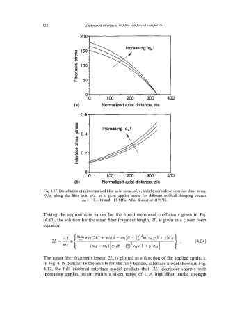
Fig. 4.17. Distribution of (a) normalized fiber axial stress, .;/a, and (b) normalized interface shear stress,
q/u, along the fiber axis, z/a, at a given applied stress for different residual clamping stresses
qa = -7, -10 and -13 MPa. After Kim et al. (1993b).
Taking the approximate values for the non-dimensional coefficients given in Eq.
(4.80), the solution for the mean fiber fragment length, 2L, is given in a closed form
equation
The mean fiber fragment length, 2L, is plotted as a function of the applied strain, E,
in Fig. 4.18. Similar to the results for the fully bonded interface model shown in Fig.
4.12, the full frictional interface model predicts that (2L) decreases sharply with
increasing applied strain within a short range of c. A high fiber tensile strength