
Page 369 - Engineered Interfaces in Fiber Reinforced Composites
P. 369
350 Engineered inierfaces in fiber reinforced composites
damage zone is noted directly below the impact site. In contrast, in the laminates
with interleaves near the back face of the laminate, only few delaminations are
present although the number of transverse cracks increases at high impact energies.
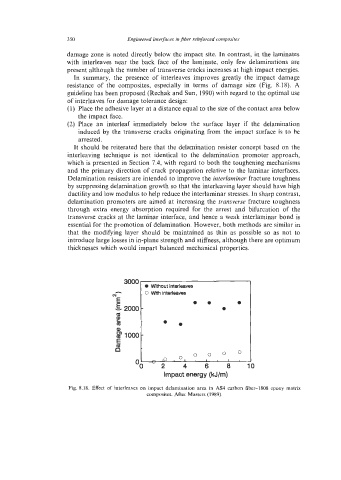
In summary, the presence of interleaves improves greatly the impact damage
resistance of the composites, especially in terms of damage size (Fig. 8.18). A
guideline has been proposed (Rechak and Sun, 1990) with regard to the optimal use
of interleaves for damage tolerance design:
(1) Place the adhesive layer at a distance equal to the size of the contact area below
the impact face.
(2) Place an interleaf immediately below the surface layer if the delamination
induced by the transverse cracks originating from the impact surface is to be
arrested.
It should be reiterated here that the delamination resister concept based on the
interleaving technique is not identical to the delamination promoter approach,
which is presented in Section 7.4, with regard to both the toughening mechanisms
and the primary direction of crack propagation relative to the laminar interfaces.
Delamination resisters are intended to improve the interlaminar fracture toughness
by suppressing delamination growth so that the interleaving layer should have high
ductility and low modulus to help reduce the interlaminar stresses. In sharp contrast,
delamination promoters are aimed at increasing the transverse fracture toughness
through extra energy absorption required for the arrest and bifurcation of the
transverse cracks at the laminar interface, and hence a weak interlaminar bond is
essential for the promotion of delamination. However, both methods are similar in
that the modifying layer should be maintained as thin as possible so as not to
introduce large losses in in-plane strength and stiffness, although there are optimum
thicknesses which would impart balanced mechanical properties.
0 Withoutinterleaves
h . 0 With interleaves
w
E 0 . 0
-E, 2000 - 0
la ..
2
la
Q) -
B 1000
E
t!
0 0
0, O
I .
0
Impact energy (kJ/m)
Fig. 8.18. Effect of interleaves on impact delamination area in AS4 carbon fiber-I808 epoxy matrix
composites. After Masters (1989).