
Page 135 - Engineering Electromagnetics, 8th Edition
P. 135
CHAPTER 5 Conductors and Dielectrics 117
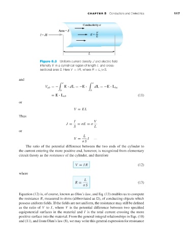
Figure 5.3 Uniform current density J and electric field
intensity E in a cylindrical region of length L and cross-
sectional area S. Here V = IR, where R = L/σ S.
and
a a
V ab =− E · dL =−E · dL =−E · L ba
b b
= E · L ab (11)
or
V = EL
Thus
I V
J = = σE = σ
S L
or
L
V = I
σ S
The ratio of the potential difference between the two ends of the cylinder to
the current entering the more positive end, however, is recognized from elementary
circuit theory as the resistance of the cylinder, and therefore
V = IR (12)
where
L
R = (13)
σ S
Equation (12) is, of course, known as Ohm’s law, and Eq. (13) enables us to compute
the resistance R, measured in ohms (abbreviated as ), of conducting objects which
possess uniform fields. If the fields are not uniform, the resistance may still be defined
as the ratio of V to I, where V is the potential difference between two specified
equipotential surfaces in the material and I is the total current crossing the more
positive surface into the material. From the general integral relationships in Eqs. (10)
and (11), and from Ohm’s law (8), we may write this general expression for resistance