
Page 163 - Engineering Electromagnetics, 8th Edition
P. 163
CHAPTER 6 Capacitance 145
6.2 PARALLEL-PLATE CAPACITOR
We can apply the definition of capacitance to a simple two-conductor system in which
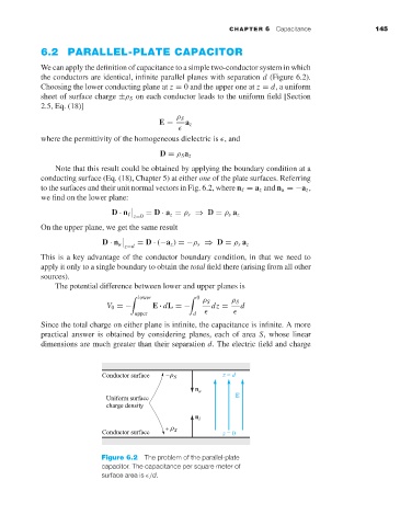
the conductors are identical, infinite parallel planes with separation d (Figure 6.2).
Choosing the lower conducting plane at z = 0 and the upper one at z = d,a uniform
sheet of surface charge ±ρ S on each conductor leads to the uniform field [Section
2.5, Eq. (18)]
ρ S
E = a z
where the permittivity of the homogeneous dielectric is , and
D = ρ S a z
Note that this result could be obtained by applying the boundary condition at a
conducting surface (Eq. (18), Chapter 5) at either one of the plate surfaces. Referring
to the surfaces and their unit normal vectors in Fig. 6.2, where n = a z and n u =−a z ,
we find on the lower plane:
D · n = D · a z = ρ s ⇒ D = ρ s a z
z=0
On the upper plane, we get the same result
D · n u = D · (−a z ) =−ρ s ⇒ D = ρ s a z
z=d
This is a key advantage of the conductor boundary condition, in that we need to
apply it only to a single boundary to obtain the total field there (arising from all other
sources).
The potential difference between lower and upper planes is
lower 0
ρ S ρ S
V 0 =− E · dL =− dz = d
upper d
Since the total charge on either plane is infinite, the capacitance is infinite. A more
practical answer is obtained by considering planes, each of area S, whose linear
dimensions are much greater than their separation d. The electric field and charge
n u
n l
Figure 6.2 The problem of the parallel-plate
capacitor. The capacitance per square meter of
surface area is /d.