
Page 166 - Engineering Electromagnetics, 8th Edition
P. 166
148 ENGINEERING ELECTROMAGNETICS
1
C =
d 1 + d 2 Area, S
e S e S
1
2
e 2 d 2
Conducting d
plates
e 1 d 1
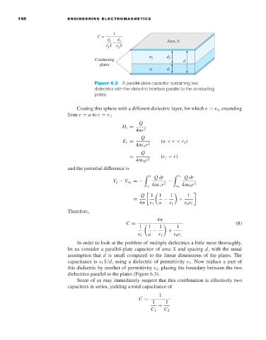
Figure 6.3 A parallel-plate capacitor containing two
dielectrics with the dielectric interface parallel to the conducting
plates.
Coating this sphere with a different dielectric layer, for which = 1 ,extending
from r = a to r = r 1 ,
Q
D r =
4πr 2
Q
E r = (a < r < r 1 )
4π 1 r 2
Q
= (r 1 < r)
4π 0 r 2
and the potential difference is
a Qdr r 1 Qdr
V a − V ∞ =− 4π 1 r 2 − 2
r 1 ∞ 4π 0 r
Q 1 1 1 1
= − +
4π 1 a r 1 0 r 1
Therefore,
4π
C = (8)
1 1 1 1
− +
1 a r 1 0 r 1
In order to look at the problem of multiple dielectrics a little more thoroughly,
let us consider a parallel-plate capacitor of area S and spacing d, with the usual
assumption that d is small compared to the linear dimensions of the plates. The
capacitance is 1 S/d, using a dielectric of permittivity 1 .Now replace a part of
this dielectric by another of permittivity 2 , placing the boundary between the two
dielectrics parallel to the plates (Figure 6.3).
Some of us may immediately suspect that this combination is effectively two
capacitors in series, yielding a total capacitance of
1
C =
1 1
+
C 1 C 2