
Page 171 - Engineering Electromagnetics, 8th Edition
P. 171
CHAPTER 6 Capacitance 153
y
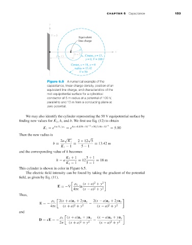
V = 0
Equivalent
line charge
x
b = 5
h = 13 Center, x = 13,
y = 0, V = 100
Center, x = 18, y = 0
radius = 13.42
V = 50
Figure 6.5 A numerical example of the
capacitance, linear charge density, position of an
equivalent line charge, and characteristics of the
mid-equipotential surface for a cylindrical
conductor of 5 m radius at a potential of 100 V,
parallel to and 13 m from a conducting plane at
zero potential.
We may also identify the cylinder representing the 50 V equipotential surface by
finding new values for K 1 , h, and b.We first use Eq. (12) to obtain
K 1 = e 4π V 1 /ρ L = e 4π×8.854×10 −12 ×50/3.46×10 −9 = 5.00
Then the new radius is
√ √
2a K 1 2 × 12 5
b = = = 13.42 m
K 1 − 1 5 − 1
and the corresponding value of h becomes
K 1 + 1 5 + 1
h = a = 12 = 18 m
K 1 − 1 5 − 1
This cylinder is shown in color in Figure 6.5.
The electric field intensity can be found by taking the gradient of the potential
field, as given by Eq. (11),
2 2
ρ L (x + a) + y
E =−∇ ln
2
4π (x − a) + y 2
Thus,
ρ L 2(x + a)a x + 2ya y 2(x − a)a x + 2ya y
E =− −
2
2
4π (x + a) + y 2 (x − a) + y 2
and
ρ L (x + a)a x + ya y (x − a)a x + ya y
D = E =− −
2
2
2π (x + a) + y 2 (x − a) + y 2