
Page 250 - Engineering Electromagnetics, 8th Edition
P. 250
232 ENGINEERING ELECTROMAGNETICS
8.2 FORCE ONADIFFERENTIAL
CURRENT ELEMENT
The force on a charged particle moving through a steady magnetic field may be written
as the differential force exerted on a differential element of charge,
dF = dQ v × B (4)
Physically, the differential element of charge consists of a large number of very
small, discrete charges occupying a volume which, although small, is much larger
than the average separation between the charges. The differential force expressed
by (4) is thus merely the sum of the forces on the individual charges. This sum, or
resultant force, is not a force applied to a single object. In an analogous way, we might
consider the differential gravitational force experienced by a small volume taken in
a shower of falling sand. The small volume contains a large number of sand grains,
and the differential force is the sum of the forces on the individual grains within the
small volume.
If our charges are electrons in motion in a conductor, however, we can show
that the force is transferred to the conductor and that the sum of this extremely large
number of extremely small forces is of practical importance. Within the conductor,
electrons are in motion throughout a region of immobile positive ions which form
a crystalline array, giving the conductor its solid properties. A magnetic field which
exertsforcesontheelectronstendstocausethemtoshiftpositionslightlyandproduces
a small displacement between the centers of “gravity” of the positive and negative
charges. The Coulomb forces between electrons and positive ions, however, tend to
resist such a displacement. Any attempt to move the electrons, therefore, results in
an attractive force between electrons and the positive ions of the crystalline lattice.
The magnetic force is thus transferred to the crystalline lattice, or to the conductor
itself. The Coulomb forces are so much greater than the magnetic forces in good
conductors that the actual displacement of the electrons is almost immeasurable. The
charge separation that does result, however, is disclosed by the presence of a slight
potential difference across the conductor sample in a direction perpendicular to both
the magnetic field and the velocity of the charges. The voltage is known as the Hall
voltage, and the effect itself is called the Hall effect.
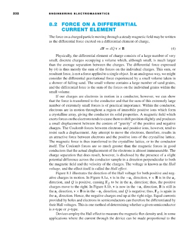
Figure 8.1 illustrates the direction of the Hall voltage for both positive and neg-
ative charges in motion. In Figure 8.1a, v is in the −a x direction, v × B is in the a y
direction, and Q is positive, causing F Q to be in the a y direction; thus, the positive
charges move to the right. In Figure 8.1b, v is now in the +a x direction, B is still in
the a z direction, v × B is in the −a y direction, and Q is negative; thus, F Q is again in
the a y direction. Hence, the negative charges end up at the right edge. Equal currents
provided by holes and electrons in semiconductors can therefore be differentiated by
their Hall voltages. This is one method of determining whether a given semiconductor
is n-type or p-type.
Devices employ the Hall effect to measure the magnetic flux density and, in some
applications where the current through the device can be made proportional to the