
Page 258 - Engineering Electromagnetics, 8th Edition
P. 258
240 ENGINEERING ELECTROMAGNETICS
and therefore
T = (R 1 − R 2 ) × F 1 = R 21 × F 1
The vector R 21 = R 1 − R 2 joins the point of application of F 2 to that of F 1 and is
independent of the choice of origin for the two vectors R 1 and R 2 . Therefore, the
torque is also independent of the choice of origin, provided that the total force is zero.
This may be extended to any number of forces.
Consider the application of a vertically upward force at the end of a horizontal
crank handle on an elderly automobile. This cannot be the only applied force, for if it
were, the entire handle would be accelerated in an upward direction. A second force,
equal in magnitude to that exerted at the end of the handle, is applied in a downward
direction by the bearing surface at the axis of rotation. For a 40-N force on a crank
handle 0.3 m in length, the torque is 12 N · m. This figure is obtained regardless of
whether the origin is considered to be on the axis of rotation (leading to 12 N · m plus
0N · m), at the midpoint of the handle (leading to 6 N · mplus6N · m), or at some
point not even on the handle or an extension of the handle.
We may therefore choose the most convenient origin, and this is usually on the
axis of rotation and in the plane containing the applied forces if the several forces
are coplanar.
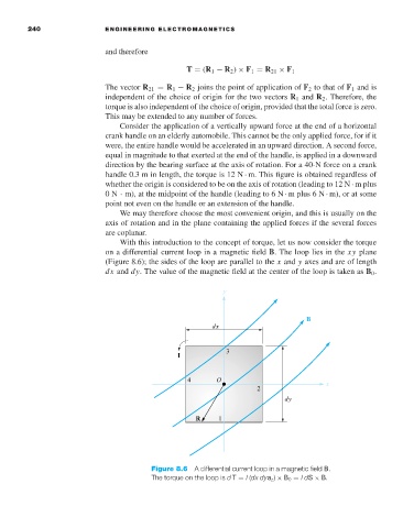
With this introduction to the concept of torque, let us now consider the torque
on a differential current loop in a magnetic field B. The loop lies in the xy plane
(Figure 8.6); the sides of the loop are parallel to the x and y axes and are of length
dx and dy. The value of the magnetic field at the center of the loop is taken as B 0 .
Figure 8.6 A differential current loop in a magnetic field B.
The torque on the loop is d T = I (dx dya z ) × B 0 = IdS × B.