
Page 256 - Engineering Electromagnetics, 8th Edition
P. 256
238 ENGINEERING ELECTROMAGNETICS
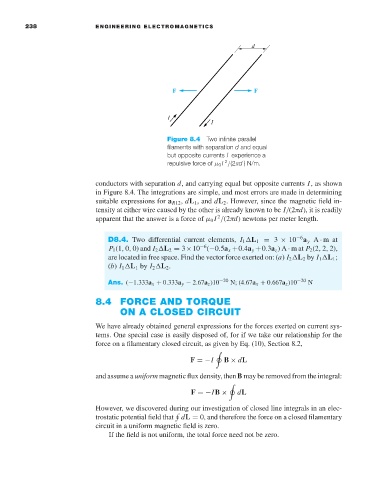
Figure 8.4 Two infinite parallel
filaments with separation d and equal
but opposite currents I experience a
repulsive force of µ 0 I /(2πd ) N/m.
2
conductors with separation d, and carrying equal but opposite currents I,as shown
in Figure 8.4. The integrations are simple, and most errors are made in determining
suitable expressions for a R12 , dL 1 , and dL 2 .However, since the magnetic field in-
tensity at either wire caused by the other is already known to be I/(2πd), it is readily
2
apparent that the answer is a force of µ 0 I /(2πd)newtons per meter length.
−6
D8.4. Two differential current elements, I 1 L 1 = 3 × 10 a y A · mat
−6
P 1 (1, 0, 0) and I 2 L 2 = 3×10 (−0.5a x +0.4a y +0.3a z )A · mat P 2 (2, 2, 2),
are located in free space. Find the vector force exerted on: (a) I 2 L 2 by I 1 L 1 ;
(b) I 1 L 1 by I 2 L 2 .
Ans. (−1.333a x + 0.333a y − 2.67a z )10 −20 N; (4.67a x + 0.667a z )10 −20 N
8.4 FORCE AND TORQUE
ON A CLOSED CIRCUIT
We have already obtained general expressions for the forces exerted on current sys-
tems. One special case is easily disposed of, for if we take our relationship for the
force on a filamentary closed circuit, as given by Eq. (10), Section 8.2,
F =−I B × dL
and assume a uniform magnetic flux density, then B may be removed from the integral:
dL
F =−IB ×
However, we discovered during our investigation of closed line integrals in an elec-
trostatic potential field that
dL = 0, and therefore the force on a closed filamentary
circuit in a uniform magnetic field is zero.
If the field is not uniform, the total force need not be zero.