
Page 327 - Engineering Electromagnetics, 8th Edition
P. 327
CHAPTER 10 Transmission Lines 309
−
−
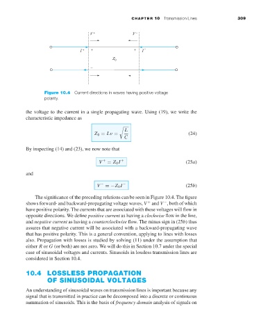
Figure 10.4 Current directions in waves having positive voltage
polarity.
the voltage to the current in a single propagating wave. Using (19), we write the
characteristic impedance as
L
Z 0 = Lν = (24)
C
By inspecting (14) and (23), we now note that
V + = Z 0 I + (25a)
and
V − =−Z 0 I − (25b)
The significance of the preceding relations can be seen in Figure 10.4. The figure
shows forward- and backward-propagating voltage waves, V and V , both of which
+
−
have positive polarity. The currents that are associated with these voltages will flow in
opposite directions. We define positive current as having a clockwise flow in the line,
and negative current as having a counterclockwise flow. The minus sign in (25b) thus
assures that negative current will be associated with a backward-propagating wave
that has positive polarity. This is a general convention, applying to lines with losses
also. Propagation with losses is studied by solving (11) under the assumption that
either R or G (or both) are not zero. We will do this in Section 10.7 under the special
case of sinusoidal voltages and currents. Sinusoids in lossless transmission lines are
considered in Section 10.4.
10.4 LOSSLESS PROPAGATION
OF SINUSOIDAL VOLTAGES
An understanding of sinusoidal waves on transmission lines is important because any
signal that is transmitted in practice can be decomposed into a discrete or continuous
summation of sinusoids. This is the basis of frequency domain analysis of signals on