
Page 425 - Engineering Electromagnetics, 8th Edition
P. 425
CHAPTER 12 Plane Wave Reflection and Dispersion 407
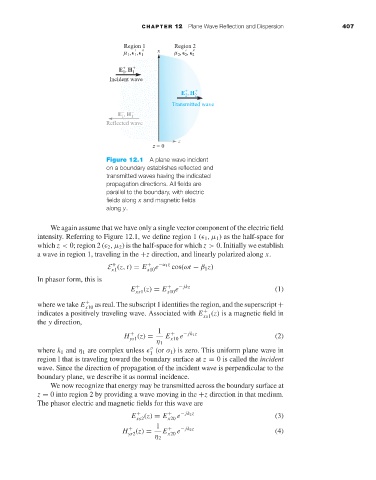
Figure 12.1 A plane wave incident
on a boundary establishes reflected and
transmitted waves having the indicated
propagation directions. All fields are
parallel to the boundary, with electric
fields along x and magnetic fields
along y.
We again assume that we have only a single vector component of the electric field
intensity. Referring to Figure 12.1, we define region 1 ( 1 ,µ 1 )as the half-space for
which z < 0; region 2 ( 2 ,µ 2 )is the half-space for which z > 0. Initially we establish
awaveinregion 1, traveling in the +z direction, and linearly polarized along x.
E (z, t) = E x10 e −α 1 z cos(ωt − β 1 z)
+
+
x1
In phasor form, this is
E + (z) = E + e − jkz (1)
xs1
x10
where we take E x10 as real. The subscript 1 identifies the region, and the superscript +
+
indicates a positively traveling wave. Associated with E + (z)isa magnetic field in
xs1
the y direction,
1
H + (z) = E + e − jk 1 z (2)
ys1
η 1 x10
where k 1 and η 1 are complex unless (or σ 1 )is zero. This uniform plane wave in
1
region l that is traveling toward the boundary surface at z = 0is called the incident
wave. Since the direction of propagation of the incident wave is perpendicular to the
boundary plane, we describe it as normal incidence.
We now recognize that energy may be transmitted across the boundary surface at
z = 0 into region 2 by providing a wave moving in the +z direction in that medium.
The phasor electric and magnetic fields for this wave are
E + (z) = E x20 e − jk 2 z (3)
+
xs2
1
H + (z) = E + e − jk 2 z (4)
ys2
η 2 x20