
Page 496 - Engineering Electromagnetics, 8th Edition
P. 496
478 ENGINEERING ELECTROMAGNETICS
d/2 θ 4
λ
(a)
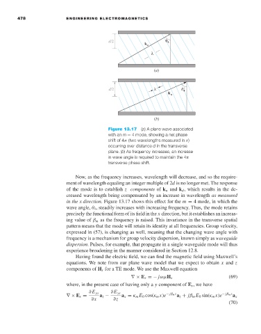
Figure 13.17 (a)A plane wave associated
with an m = 4 mode, showing a net phase
shift of 4π (two wavelengths measured in x)
occurring over distance d in the transverse
plane. (b)Asfrequency increases, an increase
in wave angle is required to maintain the 4π
transverse phase shift.
Now, as the frequency increases, wavelength will decrease, and so the require-
ment of wavelength equaling an integer multiple of 2d is no longer met. The response
of the mode is to establish z components of k u and k d , which results in the de-
creased wavelength being compensated by an increase in wavelength as measured
in the x direction. Figure 13.17 shows this effect for the m = 4 mode, in which the
wave angle, θ 4 , steadily increases with increasing frequency. Thus, the mode retains
precisely the functional form of its field in the x direction, but it establishes an increas-
ing value of β m as the frequency is raised. This invariance in the transverse spatial
pattern means that the mode will retain its identity at all frequencies. Group velocity,
expressed in (57), is changing as well, meaning that the changing wave angle with
frequency is a mechanism for group velocity dispersion, known simply as waveguide
dispersion. Pulses, for example, that propagate in a single waveguide mode will thus
experience broadening in the manner considered in Section 12.8.
Having found the electric field, we can find the magnetic field using Maxwell’s
equations. We note from our plane wave model that we expect to obtain x and z
components of H s for a TE mode. We use the Maxwell equation
∇× E s =− jωµH s (69)
where, in the present case of having only a y component of E s ,wehave
∂E ys ∂E ys − jβ m z − jβ m z
∇× E s = a z − a x = κ m E 0 cos(κ m x)e a z + jβ m E 0 sin(κ m x)e a x
∂x ∂z
(70)