Page 498 - Engineering Electromagnetics, 8th Edition
P. 498
480                ENGINEERING ELECTROMAGNETICS

                                     parallel-plate guides of orthogonal orientation that are assembled to form one unit. We
                                     have a pair of horizontal conducting walls (along the x direction) and a pair of vertical
                                     walls (along y), all of which form one continuous boundary. The wave equation in
                                     its full three-dimensional form [Eq. (59)] must now be solved, for in general we may
                                     have field variations in all three coordinate directions.
                                        In the parallel-plate guide, we found that the TEM mode can exist, along with
                                     TE and TM modes. The rectangular guide will support the TE and TM modes, but
                                     it will not support a TEM mode. This is because, in contrast to the parallel-plate
                                     guide, we now have a conducting boundary that completely surrounds the transverse
                                     plane. The nonexistence of TEM can be understood by remembering that any electric
                                     field must have a zero tangential component at the boundary. This means that it is
                                     impossible to set up an electric field that will not exhibit the sideways variation that
                                     is necessary to satisfy this boundary condition. Because E varies in the transverse
                                     plane, the computation of H through ∇× E =− jωµH must lead to a z component
                                     of H, and so we cannot have a TEM mode. We cannot find any other orientation of a
                                     completely transverse E in the guide that will allow a completely transverse H.

                                     13.5.1 Using Maxwell’s Equations to Relate Field
                                              Components
                                     With the modes dividing into TE and TM types, the standard approach is to first solve
                                     the wave equation for the z components. By definition, E z = 0inaTE mode, and
                                     H z = 0ina TM mode. Therefore, we will find the TE mode solution by solving
                                     the wave equation for H z , and we will obtain the TM mode solution by solving for
                                     E z . Using these results, all transverse field components are obtained directly through
                                     Maxwell’s equations. This procedure may sound a little tedious (which it is), but we
                                     can be certain to find all the modes this way. First, we will handle the problem of
                                     finding transverse components in terms of the z components.
                                        To begin the process, we assume that the phasor electric and magnetic fields will
                                     be forward-z propagating functions that exhibit spatial variation in the xy plane; the
                                     only z variation is that of a forward-propagating wave:
                                                          E s (x, y, z) = E s (x, y, 0)e − jβz      (76a)
                                                          H s (x, y, z) = H s (x, y, 0)e − jβz      (76b)
                                     We can then obtain expressions for the transverse components of the phasor fields
                                     by evaluating the x and y components of the Maxwell curl equations in sourceless
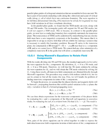
                                     media. In evaluating the curl, it is evident from (76) that ∂/∂z =− jβ. The result is

                                                            ∂E zs /∂y + jβE ys =− jωµH xs (x component) (77a)
                                       ∇× E s =− jωµH s →
                                                            jβE xs + ∂E zs /∂x = jωµH ys (y component)  (77b)

                                                          ∂ H zs /∂y + jβH ys = jω E xs (x component)  (78a)
                                      ∇× H s = jω E s →
                                                          jβH xs + ∂ H zs /∂x =− jω E ys (y component)  (78b)
                                     Now, pairs of the above equations can be solved together in order to express the
                                     individual transverse field components in terms of derivatives of the z components of

