
Page 60 - Engineering Electromagnetics, 8th Edition
P. 60
42 ENGINEERING ELECTROMAGNETICS
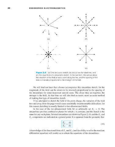
Figure 2.9 (a) One very poor sketch, (b) and (c) two fair sketches, and
(d ) the usual form of a streamline sketch. In the last form, the arrows show
the direction of the field at every point along the line, and the spacing of the
lines is inversely proportional to the strength of the field.
We will find out later that a bonus accompanies this streamline sketch, for the
magnitude of the field can be shown to be inversely proportional to the spacing of
the streamlines for some important special cases. The closer they are together, the
stronger is the field. At that time we will also find an easier, more accurate method
of making that type of streamline sketch.
If we attempted to sketch the field of the point charge, the variation of the field
into and away from the page would cause essentially insurmountable difficulties; for
this reason sketching is usually limited to two-dimensional fields.
In the case of the two-dimensional field, let us arbitrarily set E z = 0. The
streamlines are thus confined to planes for which z is constant, and the sketch is the
same for any such plane. Several streamlines are shown in Figure 2.10, and the E x and
E y components are indicated at a general point. It is apparent from the geometry that
E y dy
= (19)
E x dx
A knowledge of the functional form of E x and E y (and the ability to solve the resultant
differential equation) will enable us to obtain the equations of the streamlines.