
Page 366 - Subyek Computer Aided Design - [David Planchard] Engineering Design with SOLIDWORKS
P. 366
Fundamentals of Drawing Engineering Design with SOLIDWORKS® 2018
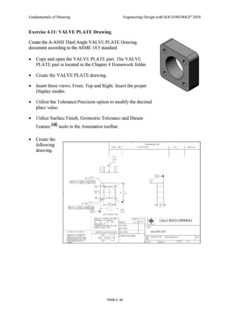
Exercise 4.11: VALVE PLATE Drawing.
Create the A-ANSI Third Angle VAL VE PLATE Drawing
document according to the ASME 14.5 standard.
• Copy and open the VAL VE PLATE part. The VAL VE
PLATE part is located in the Chapter 4 Homework folder.
• Create the VAL VE PLATE drawing.
• Insert three views: Front, Top and Right. Insert the proper
Display modes.
• Utilize the Tolerance/Precision option to modify the decimal
place value.
• Utilize Surface Finish, Geometric Tolerance and Datum
Feature~ tools in the Annotation toolbar.
• Create the
following REVISION HISTORY
ZONE REV D ESC RIPT ION DATE APPROVED
drawing.
0 .8
0 .4
\
/
j I I ol I
I o o I O I
' , , o I I
I
I O
o I o
I I O I I ! f
I A :
</) 22 +o .4
0 ~
l-$l00.2s@ I A ~@f:@ l
~ ------
,..,_,
:'\I 1
I 24 I ·- - -+- -- • 0 -
I 36 -0 .5
' -----·
I
'"
•
/ i/ - '· \
4X </)4 +o · 25 / ' 14
0 ; 2 4 I- ~ ~
12
l-$l¢0 .2s@ I A ~@b@l 0
36 · O .5
[il le i
ALL RADII 4 M M
UN LESS OTHERWISE SPECIFIED NAME DATE
D&M ENGINEERING
Dlfv\ ARE IN MILLIMETERS ~
l Pl ±.1 2Pl ±.OJ DRAWN DCP 7·201 7
ANGULAR ±.5°
INTERPRET DIM AND TOL PER CH ECKED
ASME Y14.5M· 1994 T[ LE
ENG APPR.
PIOPIIJl!IAk'I' ANO COHtOfNUA,l THIRD ANGLE PROJ ECTON MFG APPR. VAL VEPLATE
I Nf alr¢RM'-I ION ¢0N'IAlN fC> IN I HG
l>IAW• 1<. IS tHf sou ta orun' 0, /A" CONTRACT NUMBER
(liSUt1 ¢0MPAN'I' KA.Mf HU f l> . At# SIZE CAGE CODE DWG N05588·99 REV
lltP IOOUCUOIJ IM r Altl 0 1 /',$ AWKO L! A
WffHO Uf 1Ht WUUU PUIMGSION Of ,Y/
O i stlt1 COMPAt,tf MA.Mt HUE> IS ---- ISH EET Of
l'tOHltfl'fO , SCALE l w EC HT
PAGE4 - 90