
Page 160 - Engineering drawing from first principles using AutoCAD
P. 160
· Pattern development 153
co
LO
'-JOIN
R36
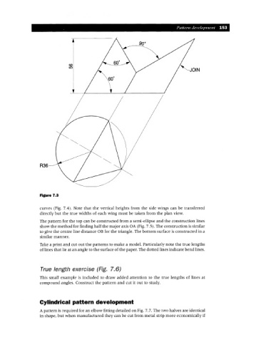
Figure 7.3
curves (Fig. 7.4). Note that the vertical heights from the side wings can be transferred
directly but the true widths of each wing must be taken from the plan view.
The pattern for the top can be constructed from a semi-ellipse and the construction lines
show the method for finding half the major axis OA (Fig. 7.5). The construction is similar
to give the centre line distance OB for the triangle. The bottom surface is constructed in a
similar manner.
Take a print and cut out the patterns to make a model. Particularly note the true lengths
of lines that lie at an angle to the surface of the paper. The dotted lines indicate bend lines.
True length exercise (Fig. 7.6)
This small example is included to draw added attention to the true lengths of lines at
compound angles. Construct the pattern and cut it out to study.
Cylindrical pattern development
A pattern is required for an elbow fitting detailed on Fig. 7.7. The two halves are identical
in shape, but when manufactured they can be cut from metal strip more economically if