
Page 189 - Engineering drawing from first principles using AutoCAD
P. 189
182 Enqineerinq drawinq }1"'0111 first principles
B
H E
o
....
~.u~-
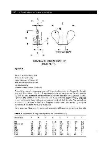
THREAD SIZE
A
STANDARD DIMENSIONS OF
WING NUTS
Figure 8.9
distance across corners 104
distance across flats 92
major diameter of thread 60
minor diameter of thread 51
nut thickness 48
chamfer radius on side of nut 60
Copy the isometric hexagon at an angle of 30° to obtain the rear profile, and line in with
polylines. Dimension 1 (Fig. 8.7) determines the length at each corner. The width of the
top face is a true dimension but the widths on the two side faces are larger and smaller.
However, the ordinates on all faces are true measurements. Position line 2 centrally
between the centre lines and their corners and mark off their lengths. The points from
ordinates 1, 2 and 3 can be lined in with a polyline then edited into a curve by using the
FIToption in the EDITPOLYLINE command.
Draw isometric ellipses for the major and minor thread diameters on the front face. The
Table 8.3 Dimensions of wing nuts in general use (refer to Fig. 8.9)
Thread size A B C D E F G H
M3 9 6.5 7 13.5 22 2.5 3.5 1.5
M4 and M5 10 8 9 15 25.5 2.5 4 1.5
M6 13 9.5 11 18 30 2.5 5 1.5
M8 16 12 13 23 38 3 6.5 2.5
M10 17.5 14 14 25.5 44.5 5 7 3
M12 19 16 15 28.5 51 5 8 3
M16 25.5 20.5 19 36.5 63.5 6.5 10 5