
Page 192 - Engineering drawing from first principles using AutoCAD
P. 192
Fastenings 185
thread pitch is 3.5 mm, and if the minor thread ellipse is copied at these pitches along the
central axis and broken at the boundaries at each end, they will at least represent the
roots and crests of the thread helices.
Construction of wing nuts
Table 8.3 and Fig. 8.9 show the dimensions of a range of wing nuts in general use. The
SCALE feature can be used to demonstrate the effect of increasing and decreasing the size
of drawings. Figure 8.10 shows the dimensions from the table for an MIa wing nut, and a
copy of the nut has been made below. The dimensions in the table are graduated
approximately in proportion to the thread sizes, so if you require an Ml6 nut you could
take a standard illustration of an MI 0 nut and increase its size using the scale feature by
1.6. Conversely, an M6 nut will be 0.6 times the size of an MIa nut. These three examples
are shown. The result of increasing and reducing sizes means that all aspects of the
drawing are changed, for example the line thicknesses, arrows and printing, as shown
in Fig. 8.11. The line thickness can always be adjusted by using the POLYLINE feature in
the Modify menu, but the arrows and text would need to be replaced.
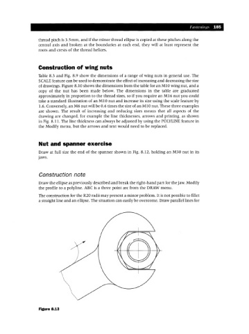
Nut and spanner exercise
Draw at full size the end of the spanner shown in Fig. 8.12, holding an M30 nut in its
jaws.
Construction note
Draw the ellipse as previously described and break the right-hand part for the jaw. Modify
the profile to a polyline. ABC is a three point arc from the DRAW menu.
The construction for the R20 radii may present a minor problem. It is not possible to fillet
a straight line and an ellipse. The situation can easily be overcome. Draw parallel lines for
Figure 8.13