
Page 195 - Engineering drawing from first principles using AutoCAD
P. 195
188 . Engineering drawinq [rom first principles
(a) (b)
Figure 9.1
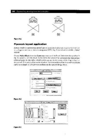
Pipework layout application
Assume symbols representing special types of motorised valves are required for insertion
on a diagram and one of them is designated SVT3. Fig. 9.1(a) shows a suitable original
symbol.
Choose Make Block from the Construct menu and the Block Definition dialogue box in
Fig. 9.2 appears. Add the Block Name and in the Select Point box insert the chosen base
reference point for the valve, which in this case can be the centre of the diagonal part of
the symbol. This point will be on the pipeline. The intersection of the X co-ordinate of 100
and Y co-ordinate of 1SO gives its position on the symbol design sheet.
Figure 9.2
a4,~Monl .dw{~ iIi
a4 ,~tdOB ~~. dw{~
a4 ,~td004 .dWf~
a4 ~MOO~).dwq
a4 ~MOOE~. dWf~
a4 ,~M(Url. dw{~
a4 ,~MOO~~. dw{~
a4~tdO'~ O.dw{~
I !iii !C~:::;?':i:;,dk;:.;': :r:::.,f"'::' • • ::.•:::::Jl;:.,.:'.:::.::.:.••':.•::.•
~
Figure 9.3