
Page 198 - Engineering drawing from first principles using AutoCAD
P. 198
Blocks and technical diaqrams 191
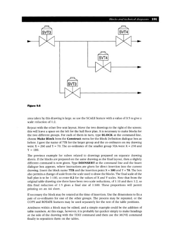
Figure 9.6
area taken by this drawing is large, so use the SCALE feature with a value of 0.5 to give a
scale reduction of 1:2.
Repeat with the other five-seat layout. Move the two drawings to the right of the screen;
this will leave a space on the left for the hall floor plan. It is necessary to make blocks for
the two different groups. For each of them in turn, type BLOCK at the command line,
choose Make Block from the Construct menu for the Block Definition dialogue box as
before. I gave the name of 7TB for the larger group and the co-ordinates on my drawing
were X = 260 and Y = 70. The co-ordinates of the smaller group sTA were X = 250 and
Y = 180.
The previous example for valves related to drawings prepared on separate drawing
sheets. If the blocks are prepared on the same drawing as the final layout, then a slightly
different command is now given. Type DDINSERT at the command line and the Insert
dialogue box appears, where instructions are given for direct insertion into the current
drawing. Insert the block name 7TB and the insertion point X =100 and Y=70. The box
also permits a change of scale from the scale used to draw the blocks. The final scale of the
hall plan is to be 1:100, so enter 0.2 for the values of X and Y scales. Note that from the
original table drawing size there have been two scale reductions, of 1:10 and then 1:2, so
this final reduction of 1:5 gives a final size of 1:100. These proportions will permit
printing on an A4 sheet.
If necessary the block may be rotated at the time of insertion. Use the dimensions to fix a
pair of co-ordinates for one of the other groups. The process may be repeated, or the
COpy and ROTATE features may be used separately for the rest of the table positions.
Attributes within a block may be edited, and a simple example could be the addition of
table numbers. At this stage, however, it is probably far quicker simply to make headings
at the side of the drawing with the TEXT command and then use the MOVE command
finally to reposition them on the tables.