
Page 203 - Engineering drawing from first principles using AutoCAD
P. 203
196 Enqineerinq drawinq [rom first principles '
cp
~
I
I~-~--l
I r'~' I I I
I I I I I
I I I I I
I I I I I
I I I I I
n I I I- ~ RADIATOR
I I I
1o--!"'1--.........---1
I I I
I I I
I
I I I
II PUMP --~
I I
I I
I I
I I
CYLINDER I I
IL_ --0
4o-J BOILER z
5
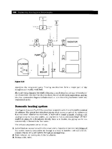
Figure 9.10
reposition the component parts. Drawing modifications form a major part of the
draughtsman's weekly work load.
Electrical wiring diagrams for suitable domestic controls fitted on this type of installation
are shown later. The true line diagram shows the actual electrical connections, and the
electrical construction diagram includes details of how the wiring has beeen routed and
constructed on site.
Domestic heating system
The diagram shown on Fig. 9.11 has now been adapted to suit a house heated by a total of
10 radiators. The system uses microbore piping which connects each of the radiators to
flow and return distribution manifolds. A manifold is simply a length of tubing with
tappings along the side and enables the engineer to run a continuous length of 8mm
small-bore piping to each radiator directly. Since it is flexible, the piping can be run
conveniently underneath the floorboards.
The various components are as follows.
1. Boiler fitted on the outside wall in the conservatory. Capacity 65 000 BTU, with balanced
flue which draws in combustion air through a concentric stainless steel duct and dis-
charges exhaust air to atmosphere through an external vent.
2. Drain valve at the lowest point in the installation.
3. Pressure relief valve.