
Page 204 - Engineering drawing from first principles using AutoCAD
P. 204
Blocks and technical diaqrams 197
~10
9
8
RADIATOR
6 13
BOILER
1
2
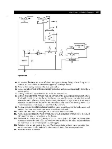
Figure 9.11
4. Air vent to discharge air manually from the system during filling. When filling water
systems, air may collect and become trapped at local high points.
5. Pump with isolating valves at the inlet and outlet.
S. Hot water valve which is thermostatically controlled and opened electrically; closed by a
return spring.
7. Heating valve with operation similar to the hot water valve.
B. Indirect domestic water cylinder with an air vent at the highest point at the inlet. Often
fitted with electric immersion heater in a boss at the top. These are expensive to use and
reheat the water relatively slowly. The internal primary coil of pipe is fed with hot water
from the central heating boiler via the thermostatically controlled heating valve. The
control thermostat is clamped to the shell of the cylinder.
9. Tapping from the top of the cylinder to the hot water connections on the bath, basins and
washer. The open expansion pipe terminates above feed tank.
10. Cold water feed from the storage tank to the bath, basins and toilet.
11. Feed tank for the domestic water system. The level is controlled by a ball valve. It is fitted
with overflow pipe to the outside of the house.
12. Feed tank to fill the boiler primary circuit at lowest point. An open expansion pipe
terminates above the feed tank. An overflow pipe is fitted to the tank. Both feed tanks
are connected to the incoming main water supply.
13. Radiator with an air vent at the top. The thermostatic radiator valve provides local
temperature control. The lockshield valve controls water flow through radiator.
14. Flow and return manifolds.